Profile Drilling Machine by Joris, Kris and Andres

Hello. You have reached this website well. We are Joris, Kris and Andres.. We are building the infinite Y axis profile drilling machine.
Below you can see an image of what is going to serve as a base for our explorations.

The idea is to rotate the bottom part of the machine by 90deg in order to make it work as the infinite Y axis mechanism. Below you can see an photo of some of the first sketches of our mechanism.

We got some parts together and decided to build a cardboard prototype first. That would let us see possible design challenges in a much more human way. For that we need cardboard and glue of course. One of the challenges here was to decide the size of the machine. If the previous day we thought 50x50cm would be the right size, today we went for 30x30cm as the right choice.
 |
 |
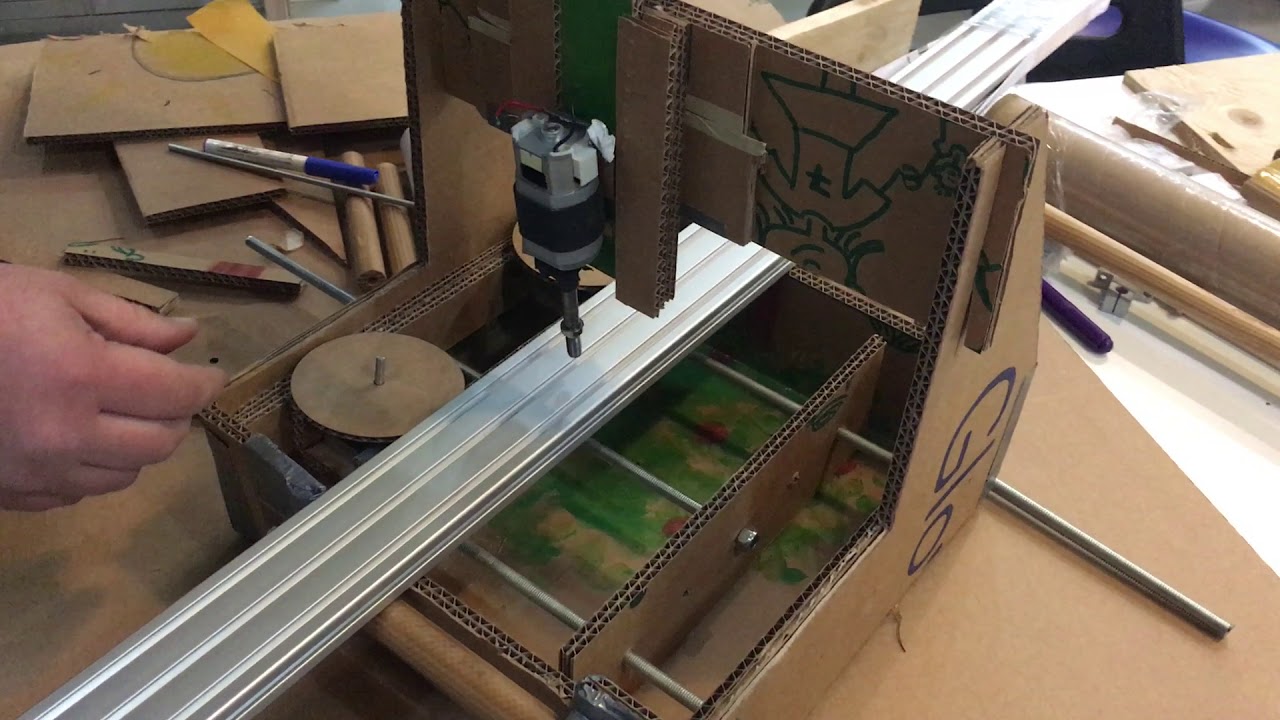
While Kris was preparing the documentation website and Andres doing research around gears, Joris was cutting cardboard and we ended up with having the following initial version of the frame.

There were a number of challenges that we identified at this point. One of them was how to mount the motors. Another how to make it easier for the profile to be drilled to move through the machine.

One more issue is where to place the electronics. How to connect the spindle motor to the Z axis? What material to use to grab the aluminium profiles to be drilled?
We arrived to a point where designing custom parts out of cardboard seemed like the right solution. We designed rolling supports for the traveling profile to be drilled and connectors for the moving clamp wheels that would keep the profile in place, letting it roll at the same time.
 |
 |
 |
 |
Below you can see a video with a brief demonstration how the machine would work.
At this point we decided that the layout is OK and we could move forward with designing the actual frame and parts. While Kris and Joris would work with the part design and mechanics, Andres would start to test the electronics. The first step in terms of electronics would be to hook up the controller with an Arduino UNO, add the motor drivers and end-stops. Use the G28 GCode to try to home the electronics system, press the end-stop and arrive to a point when the motors stop when doing that.
On the mechanical side, one has to figure out where to put the end-stops.
7 May 2018. Kris is at the Fab Lab Poerpignan with Joris. Our task for today is to create CAD drawings of the missing parts and figure out the milling process.
Joris started studying the Jen's parametric design made with Grasshopper.
Joris will prepare the Rhino design of the Jens Dyvik et al. Hattori machine. Kris will take care of designing the missing parts relative to the top part ot the Hattori machine in Fusion 360.


He tuned the GH definition and exported parts as STEP files then imported them into fusion.


It took some hours of work to get the Y axis modelled. Combining something existing made by someone else with custom design is hard. The naming of parameters and uderstanding of design software workflow varies. However there was progress and we got close to milling the parts here.

 |
 |
 |
 |
We switched from using 18mm plywood to 15mm and that is an interesting challenge always when you think that your design in Fusion 360 is truly parametric. Which it was. A bit more extra adjustments and we were able to start laying it out.

Using the Fusion 360 Dogbone addin by Case Rogers was the new experience in terms of using Fusion. Below you can see an image that shows how the dogbones look like. It was very easy, the most important part is that you have to lay the parts out on a flat contruction plane before using the Dogbone addin.

And we were ready to mill. Below you can see an image of Joris checking the milling process. There were some fails since we were in a bit of a hurry. One of the fails was that we forgot to set the Z axis before using the 8mm tool. We noticed it shortly before it was about to drill into the frame of the machine. Another thing was that we forgot to add some of the inner pockets that were supposed to create holes in some of the parts.

 |
 |
Meanwhile plastic bearing holders were being 3D printed.
 |
 |
In the left image above you can see a custom cardboard support being placed since we forgot to configure supports in Cura software. In the image to the right you can see a bearing fitting into the 3D printed part.
Meanwhile 2x Andres was working on the electronics and could not manage to get the Arduino CNC SHIELD to work. He tried many things, our hope at this point was to find help from other groups using the same board.

At this point we figured that another cycle got completed and we made a list with things that should be improved in the mechanical design part.
- Add two more rolled connectors (the plastic parts with bearings) for extra support near the Z axis.
- Add extra finger joints to connect the bottom plate of the Y axis.
- Join Y axis and X/Z axis frames together.
- Leave space all arount the clamp part.
- Add linear bearings (LM8UU) to the clamp part so it moves smoothly.
The plan was also to put Y, X and Z axes in one Fusion 360 design file.
Working on Rhino
Electronics
In this section we describe the electronics part of the machine.
Objectives
The idea is to build a 3 axis stepper motors machine. There is already an stablished harward and software to make 3-axis machines like 3d-printers, drillers, millers, ... It's GRBL. Arduino has a shield compatible with GRBL, the CNC Shield.
How a stepper motor works
<iframe width="560" height="315" src="https://www.youtube.com/embed/eyqwLiowZiU" frameborder="0" allow="autoplay; encrypted-media" allowfullscreen></iframe>A stepper motor is called this way because it rotates in small steps as some coils activate and others deactivates.
We use the CASUS Stepper Motor 42SHD0217-24B
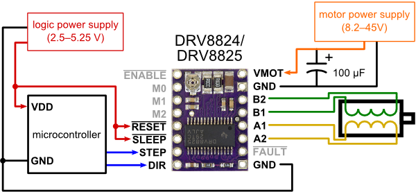
Trying Driver without shield
At first we tried to make the arduino work with the cnc shield. After many unsuccessful atemps by me and also the teachers Xavi, Santi and we tried the driver without the CNC shield to remove point of failures.
http://www.instructables.com/id/Controll-a-Stepper-Motor-With-the-DRV8825/

The driver datasheet can be found here.
int steps=9;
int dir = 8;
int stepTime=10;


void setup() {

  pinMode(steps, OUTPUT);
  pinMode(dir, OUTPUT);
  pinMode(13, OUTPUT);
  digitalWrite(13, LOW);
  digitalWrite(dir, HIGH);
}


void loop() {

  digitalWrite(steps, HIGH);
  delay(stepTime);
  digitalWrite(steps, LOW);
  delay(stepTime);
}
The result was that the motor had current and it was blocked, but not moving. Something is wrong. With the help of Mikel, we found at that the problem is in the wiring of the steppers. If the wiring is wrong and doesn't correspond with the pins in the driver then the driver is unable to coordinate the steps.
If you have four pins, lets call the ABCD, and you rearrange as DCBA, then the stepper just change directions. But if you rearrange as ABDC or BACD then in one steps goes in one direction, but then in the next step goes in the other direction. In this case the stepper just blocks. It's not able to rotate the shaft.
Here is a small video that I found about how to test the wires in a stepper.
<iframe width="560" height="315" src="https://www.youtube.com/embed/S0pGKgos498" frameborder="0" allow="autoplay; encrypted-media" allowfullscreen></iframe>So lesson learned: don't trust the given wiring of a stepper, make your test, review the datasheet.
A bit more explanation about DRV8825 and microsteppings: https://www.luisllamas.es/motores-paso-paso-arduino-driver-a4988-drv8825/
Using a CNC shield
After making the stepper work the next step is to make it work with the CNC Shield.
Here is a tutorial to make the CNC shield work. The tutorial is wrong about motor current and ground wiring.

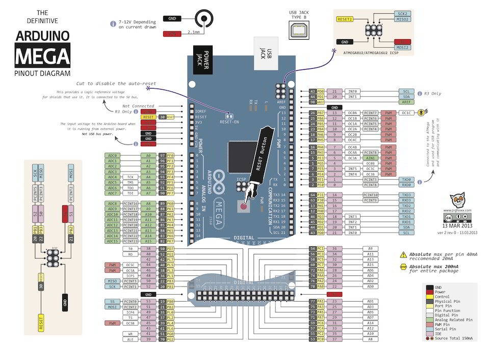
In the schematics above we can see the arduino cnc shield settings.

The Arduino CNC shield is compatible with GRBL, above we can see the pin layout to test the app.
The Arduino CNC Shield requires a driver. We use the Pololu Stepper Driver DRV8825
The CNC Shield has 3 jumpers that specifies the driver mode. It allows to control the steps size of the motor.

First I test with a similar program that the previous code without a stepper.
#define EN        8

//Direction pin
#define X_DIR     5
#define Y_DIR     6
#define Z_DIR     7

//Step pin
#define X_STP     2
#define Y_STP     3
#define Z_STP     4


//DRV8825
int delayTime=30; //Delay between each pause (uS)
int stps=6400;// Steps to move


void step(boolean dir, byte dirPin, byte stepperPin, int steps)

{

  digitalWrite(dirPin, dir);

  delay(100);

  for (int i = 0; i < steps; i++) {

    digitalWrite(stepperPin, HIGH);

    delayMicroseconds(delayTime);

    digitalWrite(stepperPin, LOW);

    delayMicroseconds(delayTime);

  }

}

void setup(){

  pinMode(X_DIR, OUTPUT); pinMode(X_STP, OUTPUT);

  pinMode(Y_DIR, OUTPUT); pinMode(Y_STP, OUTPUT);

  pinMode(Z_DIR, OUTPUT); pinMode(Z_STP, OUTPUT);

  pinMode(EN, OUTPUT);

  digitalWrite(EN, LOW);

}

void loop(){

  step(false, X_DIR, X_STP, stps); //X, Clockwise
  step(false, Y_DIR, Y_STP, stps); //Y, Clockwise
  step(false, Z_DIR, Z_STP, stps); //Z, Clockwise

  delay(100);

  step(true, X_DIR, X_STP, stps); //X, Counterclockwise
  step(true, Y_DIR, Y_STP, stps); //Y, Counterclockwise
  step(true, Z_DIR, Z_STP, stps); //X, Counterclockwise

  delay(100);

}
Adding the endpoint
We test the CNC Shield with the endpoint.
The diagram of the endpoint is:

The code, we just remove the endpoint part ofthe code, because the value is proportionated by the endpoint:
#define EN        8

//Direction pin
#define X_DIR     5
#define Y_DIR     6
#define Z_DIR     7

//Step pin
#define X_STP     2
#define Y_STP     3
#define Z_STP     4


//DRV8825
int delayTime=30; //Delay between each pause (uS)
int stps=6400;// Steps to move
int i = 0;

void step(boolean dir, byte dirPin, byte stepperPin, int steps)

{

  digitalWrite(dirPin, dir);

  delay(100);

  for (int i = 0; i < steps; i++) {

    digitalWrite(stepperPin, HIGH);

    delayMicroseconds(delayTime);

    digitalWrite(stepperPin, LOW);

    delayMicroseconds(delayTime);

  }

}

void setup(){

  pinMode(X_DIR, OUTPUT); pinMode(X_STP, OUTPUT);

  pinMode(Y_DIR, OUTPUT); pinMode(Y_STP, OUTPUT);

  pinMode(Z_DIR, OUTPUT); pinMode(Z_STP, OUTPUT);

  pinMode(EN, INPUT);

  //digitalWrite(EN, LOW);

  Serial.begin(9600);
}

void loop(){
  Serial.print(i++);
  Serial.println(" looping");
  step(false, X_DIR, X_STP, stps); //X, Clockwise
  step(false, Y_DIR, Y_STP, stps); //Y, Clockwise
  step(false, Z_DIR, Z_STP, stps); //Z, Clockwise

  delay(100);

  step(true, X_DIR, X_STP, stps); //X, Counterclockwise
  step(true, Y_DIR, Y_STP, stps); //Y, Counterclockwise
  step(true, Z_DIR, Z_STP, stps); //X, Counterclockwise

  delay(100);

}Change to Arduino RAMPS v1.4
There is a problem with the Z-Axis in the Shield. We tried the motors (all work), the drivers (all work) but the z-axis in the shield doesn't work.
So we change to an Arduino RAMPS (5 axis controller)


Configure Marlin with Arduino
Arduino RAMPS requires of the Marlin software no manage the steppers.
We follow this tutorial
to install the firmware.
http://archive.fabacademy.org/2017/fablabvigyanashram/machine.html
Inside the Marlin source code is Configuration.h with all the defines for configurating the system. We change the BAUD_RATE to 9600.
Configura Arduino Ramps Endpoints
Follow this tutorial
What is GRBL?
GRBL is a firmware to control 3 axis machines.
We follow this tutorial to learn what is GRBL.
GRBL uses G-CODE protocol to communicate instruction between the program and the robot. For example
https://www.simplify3d.com/support/articles/3d-printing-gcode-tutorial/
# Go fast to position 0,0,0
G00 X0Y0Z0

# Go slowly and straight to high 1mm with speed of 5mmm/minute (feed rate). Used when machine is cutting and the route is important.

G1 Z100 F50
GRBL does Look Ahead Planning to calculate when accelerate and deaccelerate to make straight lines.
Here you have many GCode Examples I tried many examples using just the serial port.
To test sending G-CODE from Ubuntu Universal G-Code Sender
GRBL Setting
I follow this tutorial
Fabricating X/Z axis
According to the model we made on fusion, joris generated in Rhino/Grassopper a full X-Z axis system for the 8mm thick HDPE material found. Then started creating the startegies under RhinoCAM in order to mill the rack and pinions with HDPE.


Finally he finished the strategies only the Thisday of the next week 14 strategies and milled all the parts on the friday. The hard point was to find the bits needed (3.175 mm, 1.85mm, 90° V, 6 mm). 2 hours of of milling, 3 tool changes, but the result is satisfying.
For the feeds and speeds joris used the Fablab Speed and Feeds Calculator and the jake Read's machine week document.


Here is a resume of the strategies:

And some videos showing the milling process:


Assembling
The most difficult part of the assembly was to find the bolts, the screws and the nuts. At the end of the day, Santi came to "Chino" to buy some little bolds.
Finally, we make some manual adjustments drilling screwing and cutting, and we had this first version of the frame.

Here you can see the result at cardboard version's side.

The week after Kris couldn't be available bacause he had to travel to give workshops. Andrés was still working on the electronic and the command. Since we decided swithed to Ramps, he was still fighting to tune the motors. He suspected the motors tobe the cause of the troubles so he orederd new ones.
After a bunch of test and adjustements, we managed to make it move.

joris took back home in France the machine and continue working on the integration.


he designed some extra parts, like endstop supports, and Y axes wheel with its motor support.
Finally he milled in wood the wheel and 3D print a part between the motor shaft and the wooden wheel.


Some times it took several iterations to obtain the good part.

For the tool, that will be a dremel, Joris found on thingiverse a model he edit to fit on our system.
Original design : Support for Dremel 4000 by bqLabs - CC - BY - SA


Finally make all assembly clean, with a proper cable management.

Controlling:
We decided to setup a CNC compatible firmware called Repetier. It could have been Marlin, but Joris knew there is a special integration of CNC machining on repetier, mainly known as a 3D printer firmware.
The firmware comes with a software called Repetier Host

There is a special online Wizard to tune your firmware depending on your machine.
Here are all the steps, you can see the different value choosen :


Once we defined your settings, we downloaded the firmware we put on the arduino mega.
Unziped the downloaded archive, open .ino file with Arduino IDE. Connect your ramps and upload the code to the arduino as shown bellow.

Now dowload and install the Repetier Host that we use for driving the machine manually sending GCode.
The UI look like that.
Set up connection settings to connect the computer to the arduino/ramps.

We tuned the machine settings like the number of step/mm for each motors, accelerations and moves speed. Those values are stored in the arduino EEPROM (Menu->Configuration-> EEPROM firmware configuration).

We wrote some g-code to create a sample move, but you could also use your favorite CAM software to generate the gcode.

Basicaly the gcode is for drilling 2 holes, that way we can see all axes moving.

Memo about gcode : http://linuxcnc.org/docs/html/gcode.html
Final result
Here is an hero shot of the machine.
Want to see it in action ? Click on the image.

Also available in better quality on youtube.
Things to improve / limitations
- material Z homing
- y wheel support
- A third bearing tube near the spindle
- Change the spindle, cause not powerfull engough
- Use better tools