The Iris : Design, Fabrication and Actuation
Design : Initial approach
Looking at designing the Iris, we decide to invest in a online iris generator. Calculating the exact design of each leaf is a delicate exercise, and the people behind this website are former camera designer, and can be trusted when it comes to designing any diaphragm with precision.
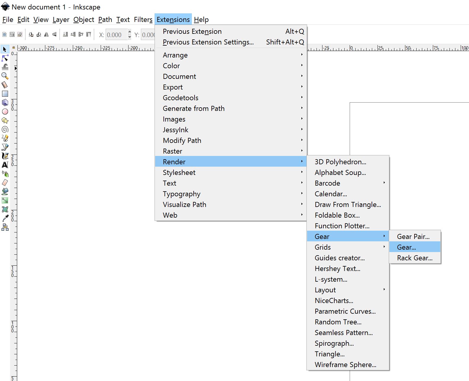
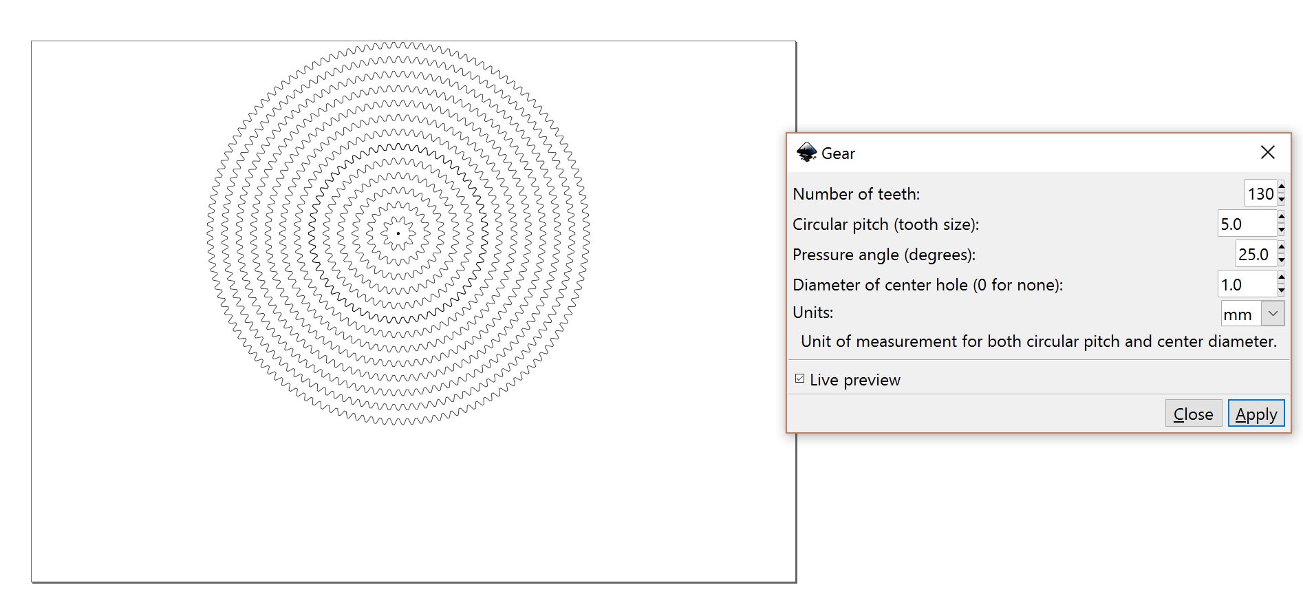
We then look for a automated system to design the gears. Inkscape offers such system, allowing us to set up a diameter of our gear. For testing purpose we design several gears with the same teeth size but a different amount of them. This way we will be able to test and choose from many options for both the iris ring and the gear attached to the servo motor.
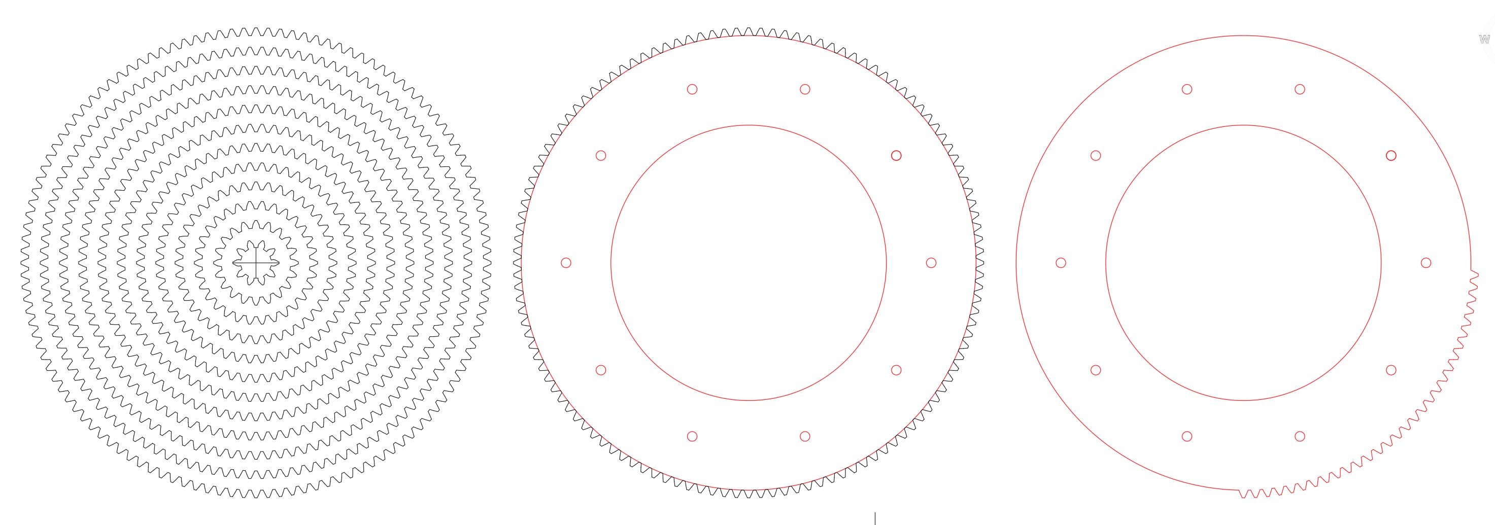
We exported the file in .dxf so we can work more confortably in Autocad. For the Iris ring, we select a gear displaying 120 teeth. The size is not perfectly the one required, so we scaled all the gears to match the actual sinze of iris ring. We then delete all uncessessary teeth for motion, as designed by the Iris Calculator.
For the servo motor, we design several rings with different sizes to choose from later on. The design of the leafs are paired and nested to fit within a A4 sheet of thick colored paper.
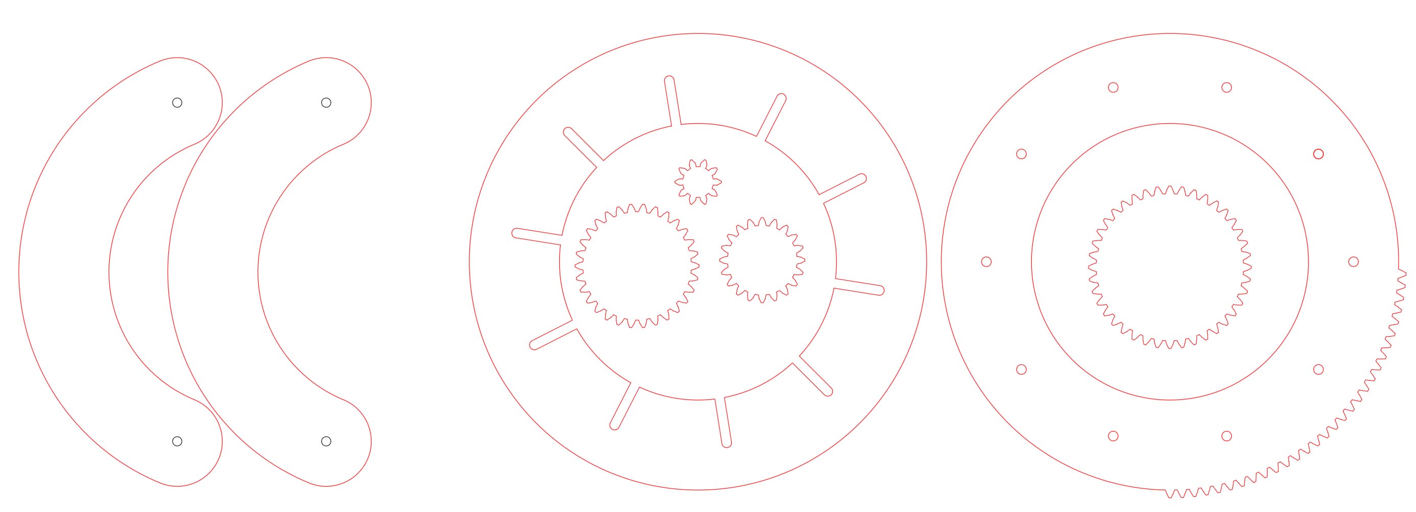
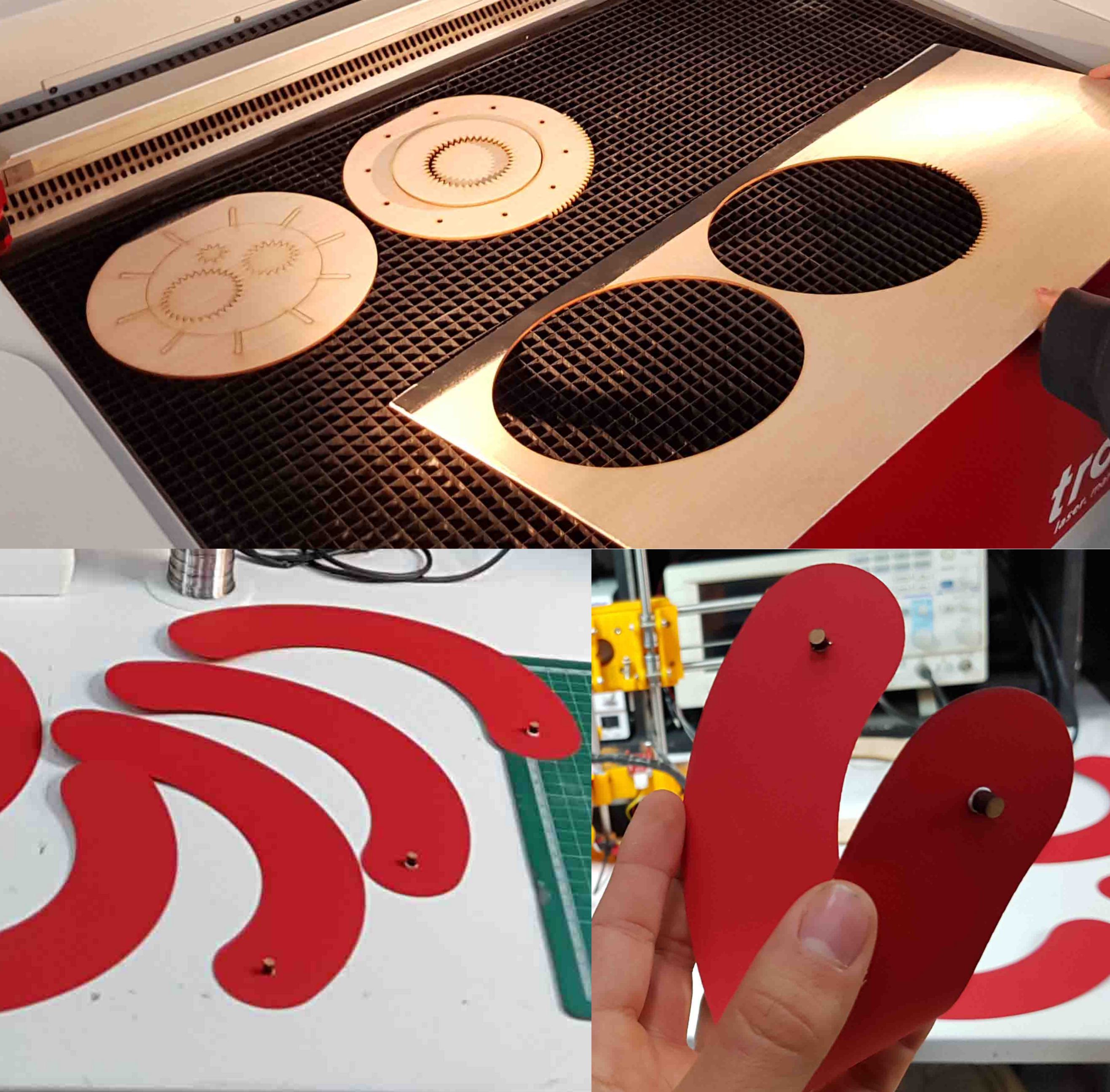
The result is promising, all leafs are sliding nicely, and the overall motion is smooth.
Design : development
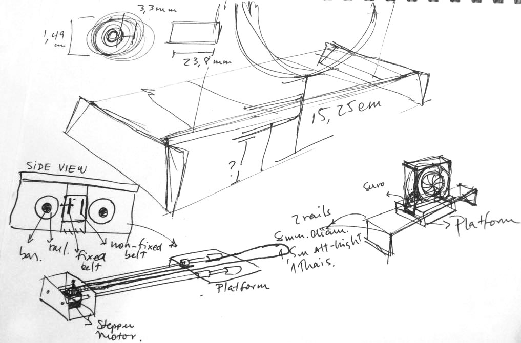
We sketch the overall design of the machine to have abetter grasp on how it will fit together.
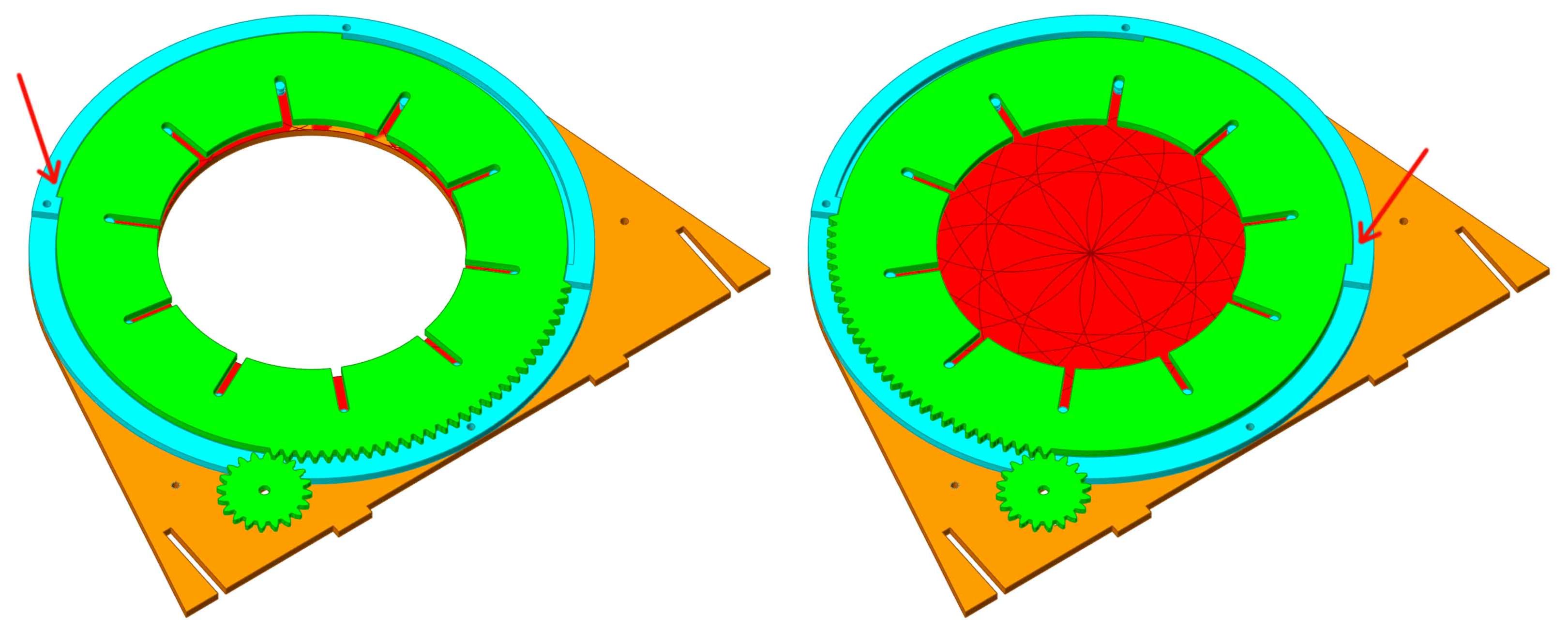
We model the iris part in Rhino. The iris consists of:
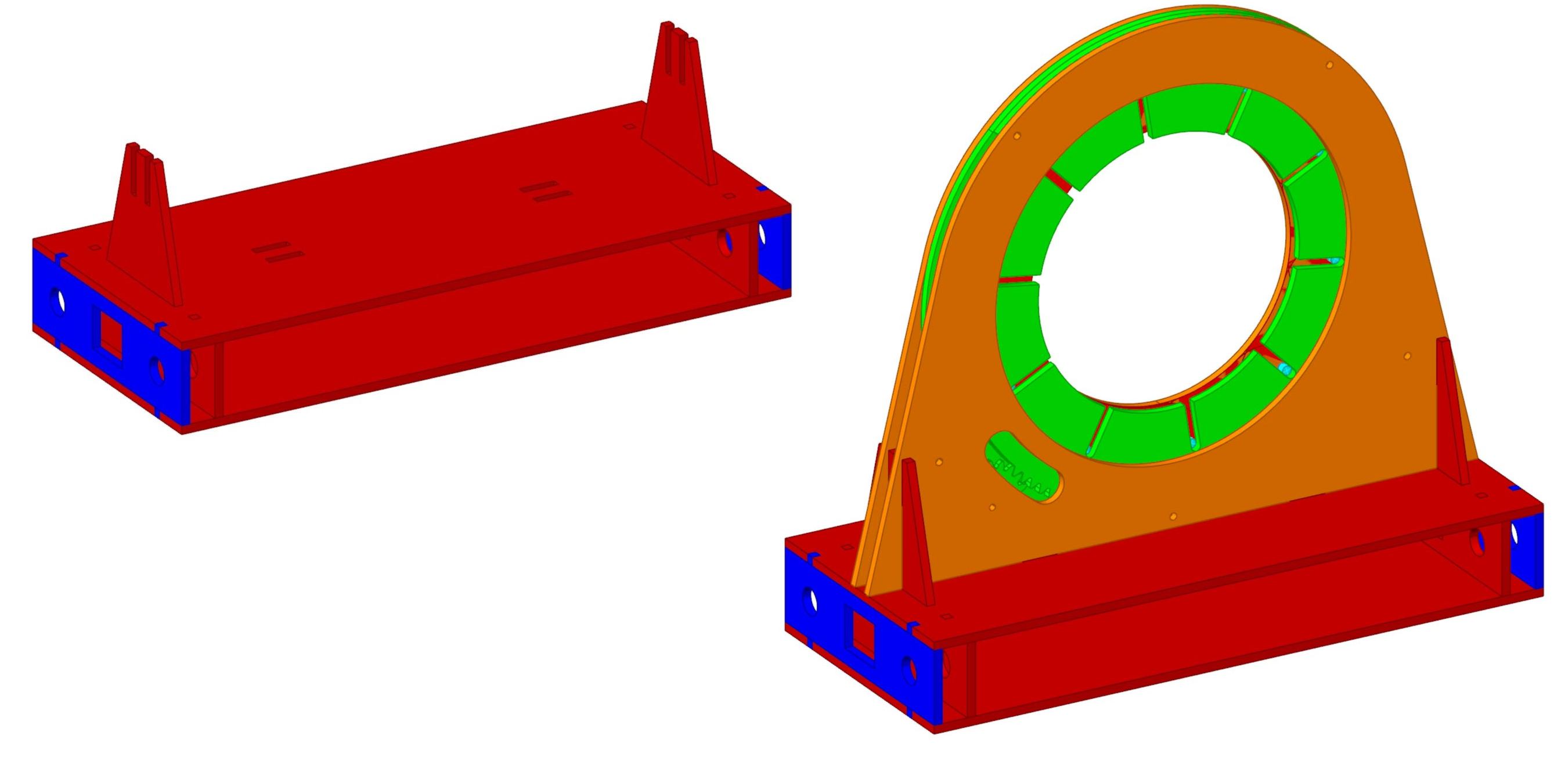
- two pieces (in orange below) placed on the top and bottom of the structure, holding everything together;
- many leaves (in red), each of them having pins (in blue) glued to both ends. On one end, pins are looking up, while on the other pins are looking down. Bottom pins fit into holes located on the bottom structure (fixed), while top pins fit in the top ring (in green), which motion will drive the motion of the leaves;
- The blue ring provides enough space for the leaves and the blue half ring to rotate freely. Attached to the servo is another smaller gear (in green) which will drive the entire "actuator ring".
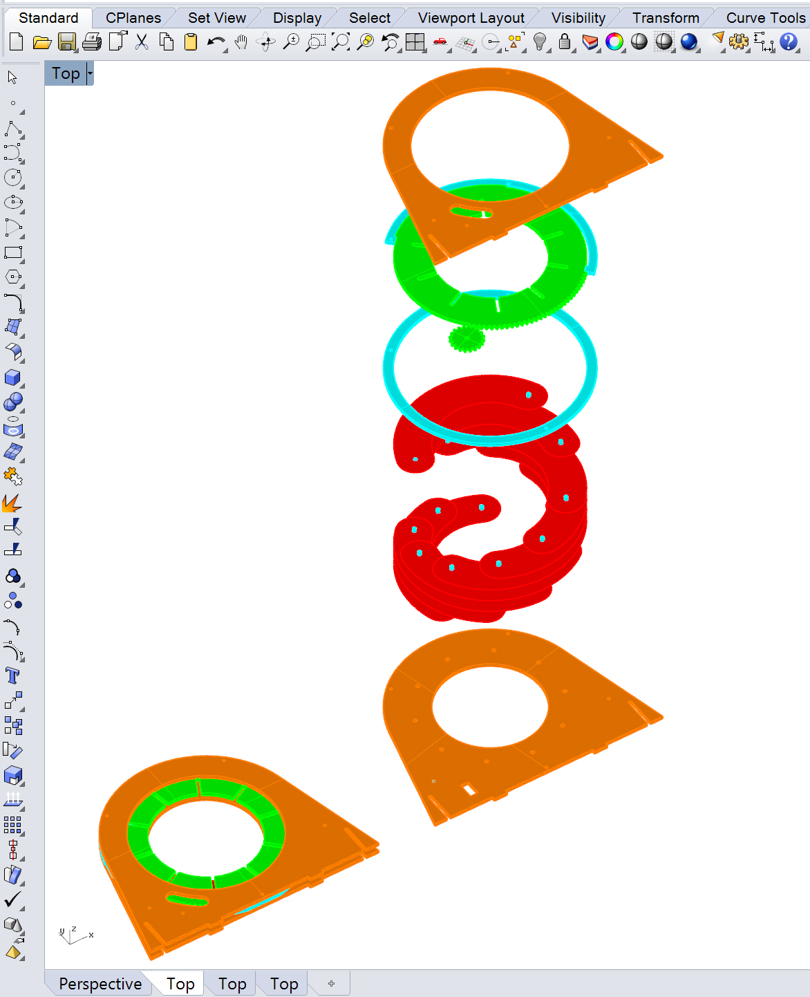
Notice how the actuator ring (in green) only spins up to the right angle when opening (left) or closing (right) in order to avoid breaking the mechanism.Part of the casing stays clear so we display the inner mechanism.
The platform on which the iris sits is designed and added to the assembly.
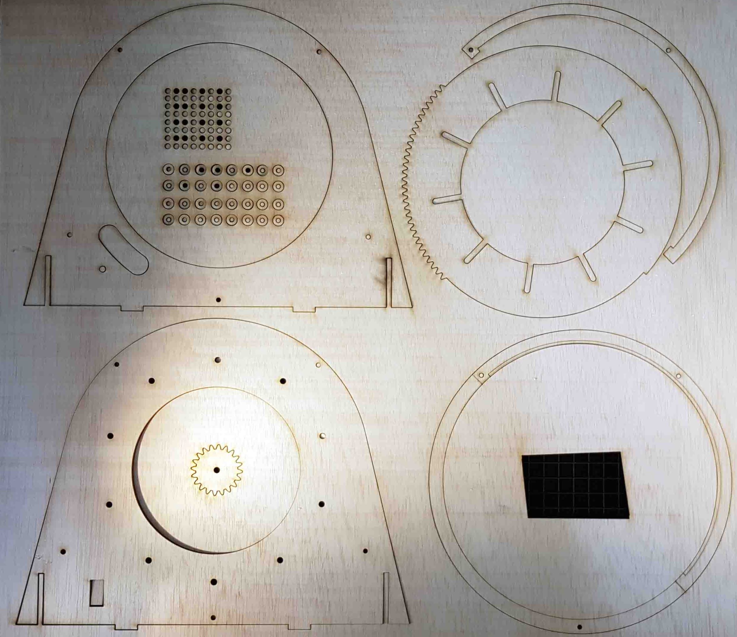
The design is sent to the laser cutter. we use a sheet of 5mm plywood, cut with the following settings :
- Cutting: Power 100, Speed 1. 1000Hz;
- Engraving: Power 20, Speed 3. 1000Hz
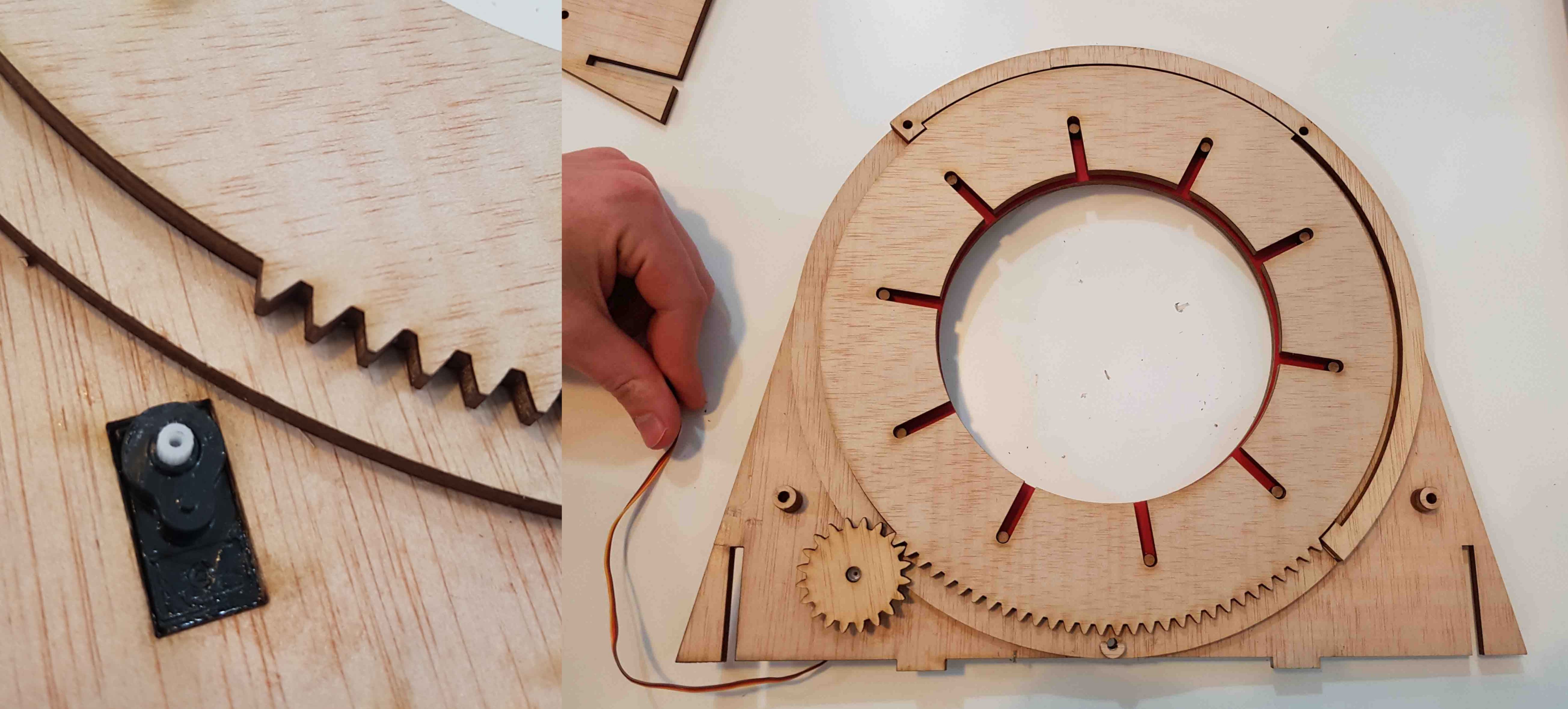
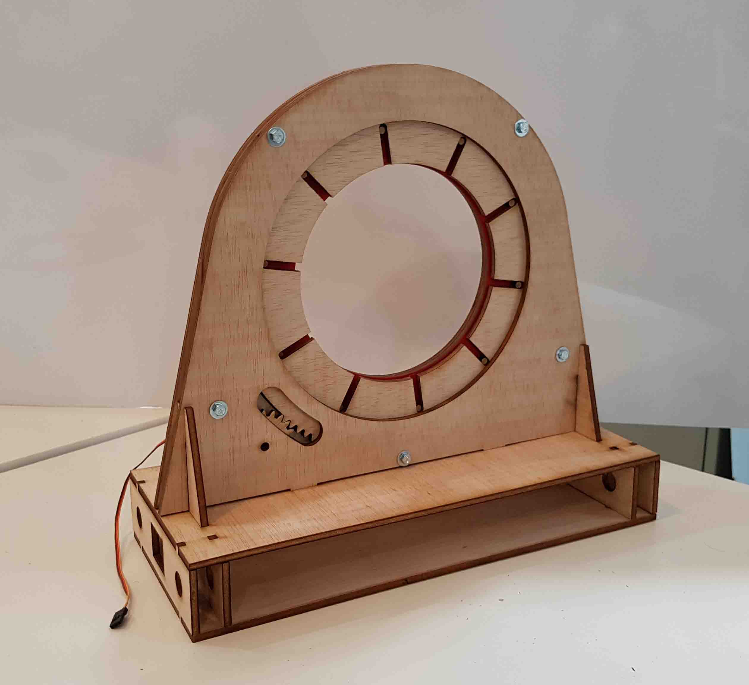
We cut a section to fit the servo motor, which is then glued into place. At this stage we are uncertain whether the actuator ring will spin smoothly. There is a bit of friction happening...
Actuation : calibration of the servo
The iris works fairly well but some changes are required.
Firstly, we didn't know servo motors usually only spin 180 degrees, which si not enough to spin the actuator ring all the way. The iris cannot close fully. In order to fix this, the servo needs to be changed to a Continuous Rotation Servo (SM-S4303R). Luckily we have one in the lab.
Continuous Rotation Servos are actually not standard servos because they cannot be commanded to go to a specific position and stop, and apparently there is no way arduino can tell what position it is at at any specific time. In short these servos have no feedback system. What we have now is a variable speed bi-directional geared motor, not a servo. The explanation of why it is called a servo is that it starts life out as a complete standard servo, then they remove the internal geared feedback to the internal pot and also remove the mechanical end stops on the gear train, which then makes it a variable speed bi-directional geared motor drive. However we'll keep calling it 'servo'.
This new servo is bigger and stronger, which will be better to spin the actuator ring. That also means the hole designed for the motor has changed. Some pieces were cut to make a frame for the motor so it is correctly fastened to the structure.
Secondly, the actuator ring generate friction with the rest of the frame. To fix this some changes were made:
- changing the actuator ring from 5mm to 3mm plywood;
- reducing the quantity of surface in contact with the frame. Sanding the edge of the pieces seems to improve the motion. The laser browned edges seem more sticky than the original wood texture and the actuator ring sometimes got stuck, overloading the servo motor.
Thirdly, the press-fit assembly for the iris to the platform was too far on the side, which made the wood weak and easy to break. To solve this, the slots were moved towards the inside of the structure.
Everything seems to be working properly after these changes, so it is time to assemble of the new iris. Before closing the whole mechanism, we tried to program the servo and see its response. However it is not responding how it should. It moves in a weird way and stops unexpectedly. Finally we realise where the problem comes from : the servo is not calibrated. That is our next step.
For the calibration we will use the following code:
#include Servo servoRotCont;
void setup() {
servoRotCont.attach(9);
}
void loop() {
servoRotCont.write(90);// STOP
}
After running this code, the servo motor should come to a stop. If the gear still moves,it means the motor is not calibrated. We test it, however...
...It is still moving. It requires a manual calibration. We use a screwdriver to access the potentiometer. One direction makes it move faster, while the other one slows it down. We rotated it until it comes to a stop.
Actuation : programmation
We can now move to the programmation part. A continuous rotation servo doesn't work in the same way as a standard servo: you can't choose the angle you want it to rotate to. But you can choose the direction of rotation, the speed and the time (delay). This is not as precise as a standard servo but using the three other settings, we are able to achieve similar level of control.
However this is tricky: For example, to move the actuator ring gear all the way (30 teeth) means moving the servo gear (20 teeth) one and a half turns (20teeth*1.5=30teeth). This would be easy if we could program de motor to rotate 360+180 degrees but we can't do it this way. We need to set a direction and a speed and calculate the time it takes to rotate the desired angle. We also need to consider that the motor gear doesn't rotate at the same speed when completely free as when there is some resistance (the actuator ring gear). This means different delay time for the same angle depending on the resistance and also the orientation of the gear (it doesn't rotate the same speed when horizontal than when it is vertical, because the weight of the actuator ring also slows down the motor gear). So, we decided to assemble everything and orient the iris vertically, because this is how the machine will finally be. We then start playing with the correct rotation time.
So far, we decided to make the iris go through a serie of motion. We test it out and decide on the following motion and timing:
- Close the iris completely;
- Open the iris completely (2400 milliseconds);
- Close the iris to position 1 (650 milliseconds);
- Close the iris to position 2 (650 milliseconds);
- Close the iris to position 3 (650 milliseconds);
- Open the iris completely (2400 milliseconds).
Between each movement, the iris poses for a moment. Also, moving the iris to each position should be equal to the total closing time (2400 milliseconds) divided by three (2400/3=800 milliseconds). However for some reason it doesn't work like this and 650 milliseconds for every step seems to work better.
Find below the code used :
#include
Servo servoRotCont; // crea los objetos para controlar los servomotores
void setup() {
servoRotCont.attach(9);
}
void loop() {
servoRotCont.write(0);//close
delay(2400);
servoRotCont.write(90);//stop
delay(2000);
servoRotCont.write(180);//open
delay(2400);
servoRotCont.write(90);//stop
delay(2000);
servoRotCont.write(0);//close to 1
delay(650);
servoRotCont.write(90);//stop
delay(2000);
servoRotCont.write(0);//close to 2
delay(650);
servoRotCont.write(90);//stop
delay(2000);
servoRotCont.write(0);//close to 3
delay(800);
servoRotCont.write(90);//stop
delay(2000);
servoRotCont.write(180);//open
delay(2400);
servoRotCont.write(90);//stop
delay(2000);
}
Finally we get to a satisfying result!
The iris is ready to be added to the directional axis.
You can find the files ready for download on the main page.