Mechanical axis : Design, Fabrication and Actuation
Design
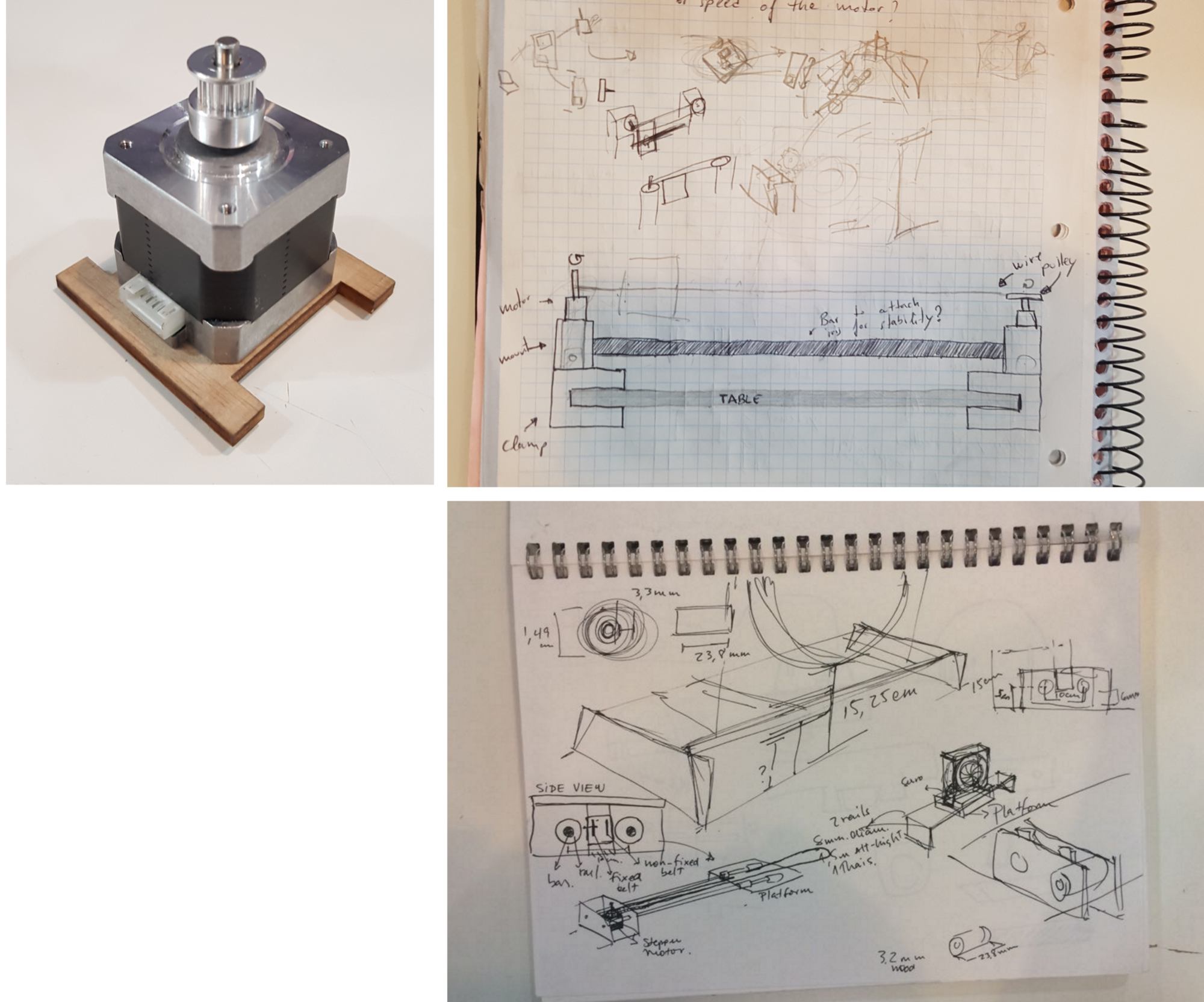
Firstly we select an actuator for size reference. After checking the material available at the lab, we select a stepper motor big enough to move the platform where the iris sits.
We then consider different options for the structure. Initially, the idea is to use some wires or cables in tension to operate the platform. These cables would be moved by the stepper motor. After a bit of research and some sketching we ruled out this possibility since it wouldn't provide enough stability : the platform that carries the iris is too heavy for such setup. So instead, we decide to design a structure including two rails for the platform to move over. We also iterate our first concept in which the support was held to the table by a pair of clamps attaching to the ping-pong table. It is limiting our options to ping-pong tables, and we'd rather make a support that could be freely used on different kind of tables.
We cut a first iteration of the rail support with the laser cutter, using 5mm plywood as a press-fit test, and add rails between them. We come up with a casing with holes between the rails that would allow the belt to run from the motor to the pulley.
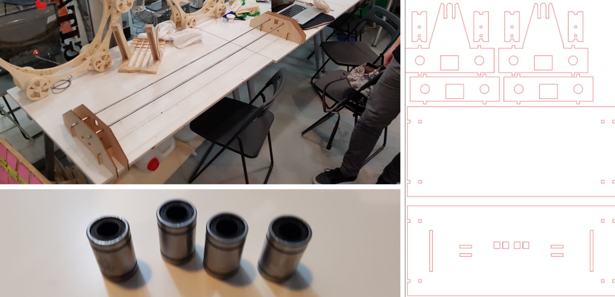
This first iteration gives us data about the amount of friction generated between the moving parts. We notice that, although the hole dimension are accurate, some extra support to hold the platform apart from each other would reinforce the overall structure. We therefore add wooden rings tightly fitted to the rails and located against the lateral supports.
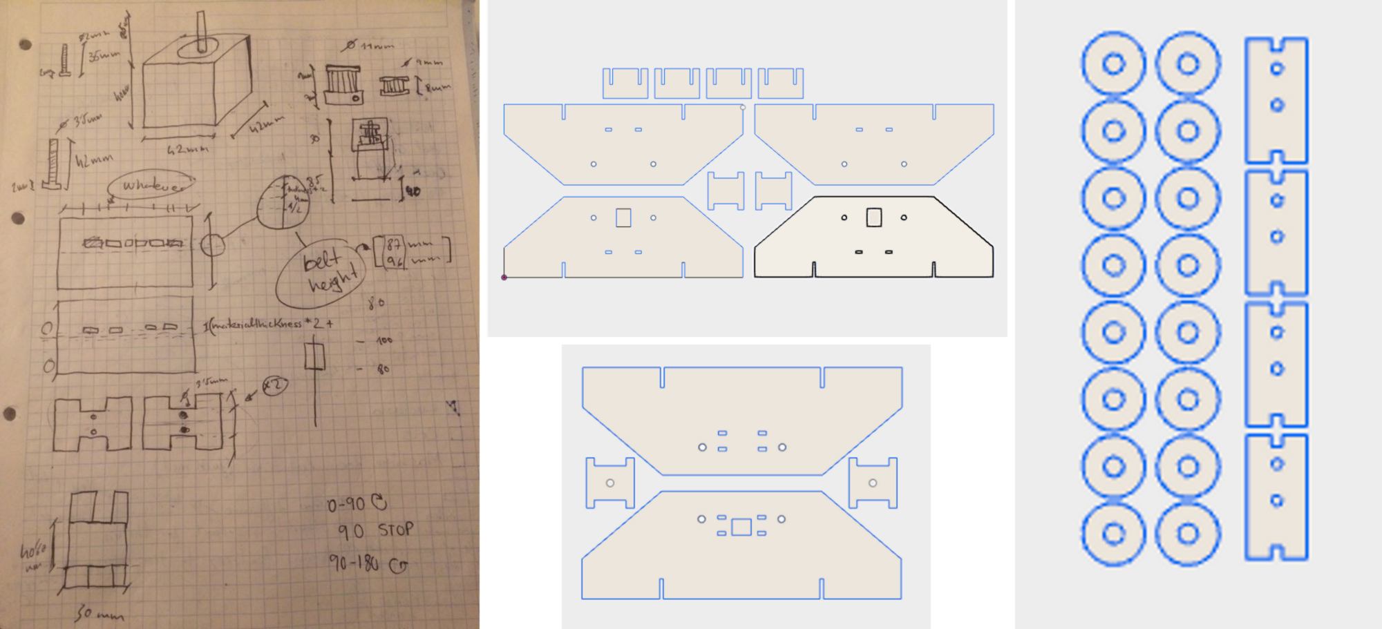
A modification is made to the platform where the iris sits to adjust and tighten the belt. Also, bearings are added to the platform to ensure the sliding motion is smooth.
We finally re-make one of the lateral supports to adjust the height of the hole where the belt runs through.
Actuation
It is time to program the stepper motor. But first, what is it actually, a stepper motor?
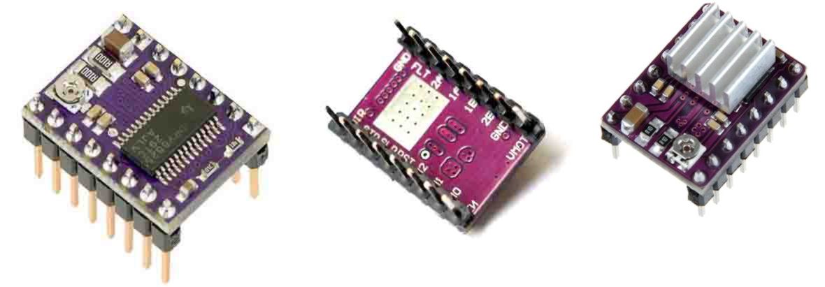
To control the motor, we will use the DRV8825 Stepper Motor Driver Carrier. When running, the driver gets extremely hot. For this reason it comes with a heatsink that is stuck to the microcontroller to dissipate the heat.
There is an Arduino-compatible shield with these drivers. Like other shield, it goes on top of the Arduino board and connects the arduino to the driver. However, after assembling everything and uploading some code to the microcontroller, the motor is not working properly. The motor makes some noise but it does not move. We Try to adjust the potentiometer of the driver using a screwdriver without any success.
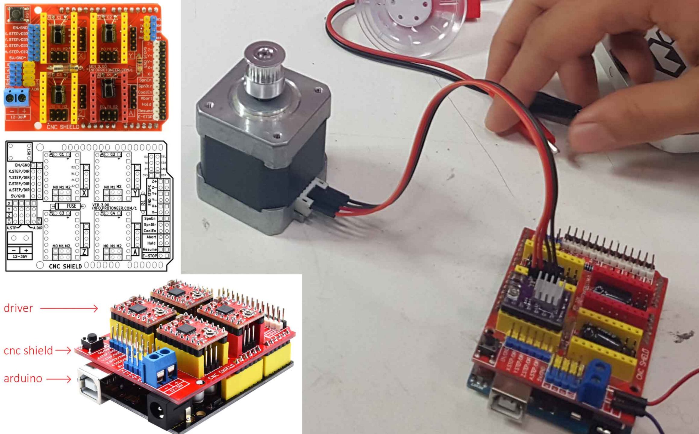
Mikel comes over to give us some help. He believes that it is a hardware issue, thinking that the CNC shield is not working correctly. He recommends to directly use a driver, set it up on a proto board and use jumpers to connect all parts together.
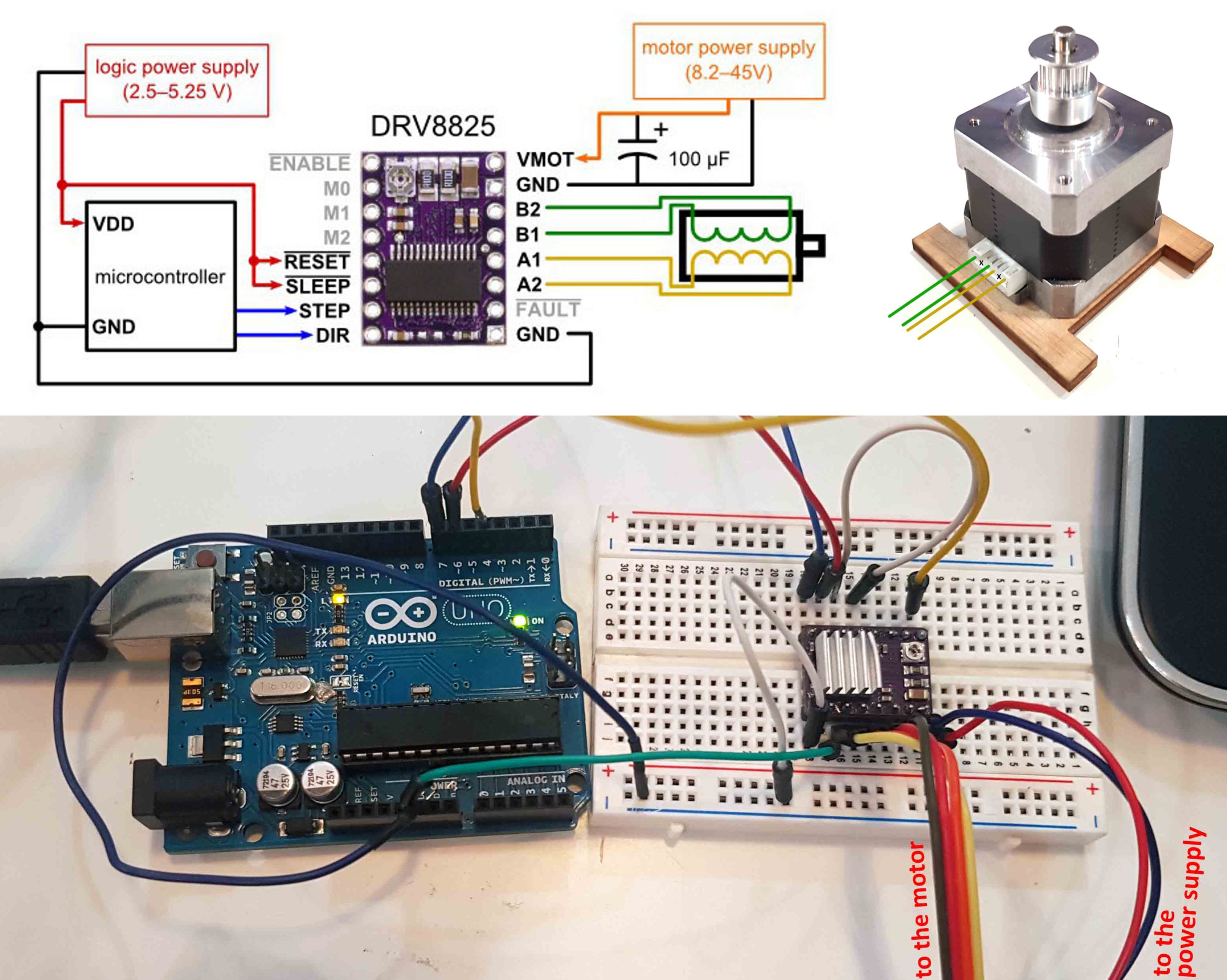
We get to learn more about the driver pinout. A1 and A2 (yellow) are connected to one of the coils in the stepper motor (first and third pin). B1 and B2 (green) are connected to the other coil (fourth and sixth pin). There are two pins in the stepper motor that are not used.
This time, the motor makes a "better" sound than before, however it is still not moving. Suspicious of our code, we ask assistance from Mikel again, who writes a test code to check the motor. After a few adjustment on the potentiometer we finally get it to work (the potentiometer is very sensitive, and very little rotation will make it work... or not).
Now that we know that the hardware is in working condition, we write some code to drive the stepper motor correctly.A mistake between using microseconds (delayMicroseconds) rather than milliseconds (delay)slows us down, butwe finally make it work. It is time to assemble it all to see it slide along.
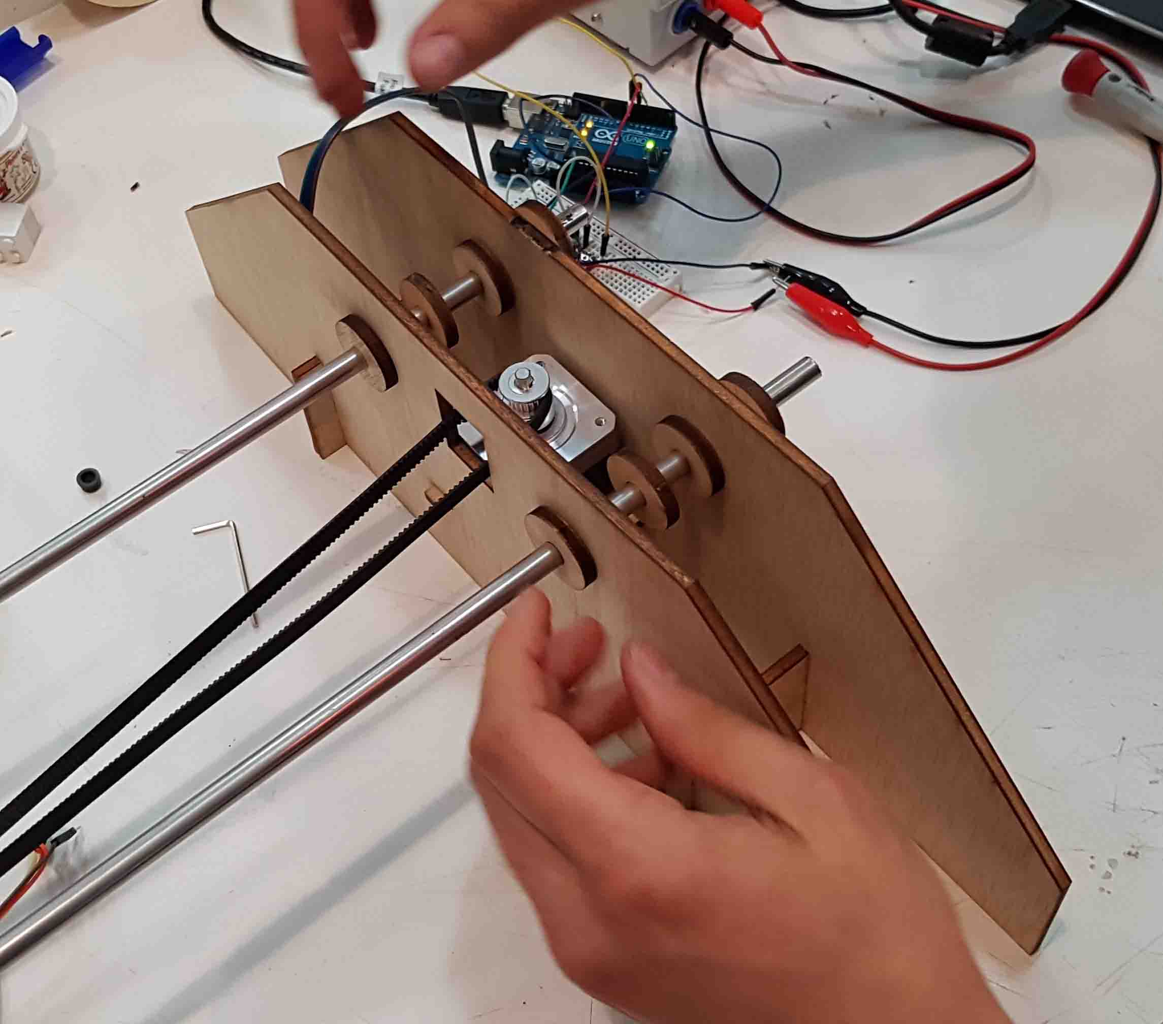
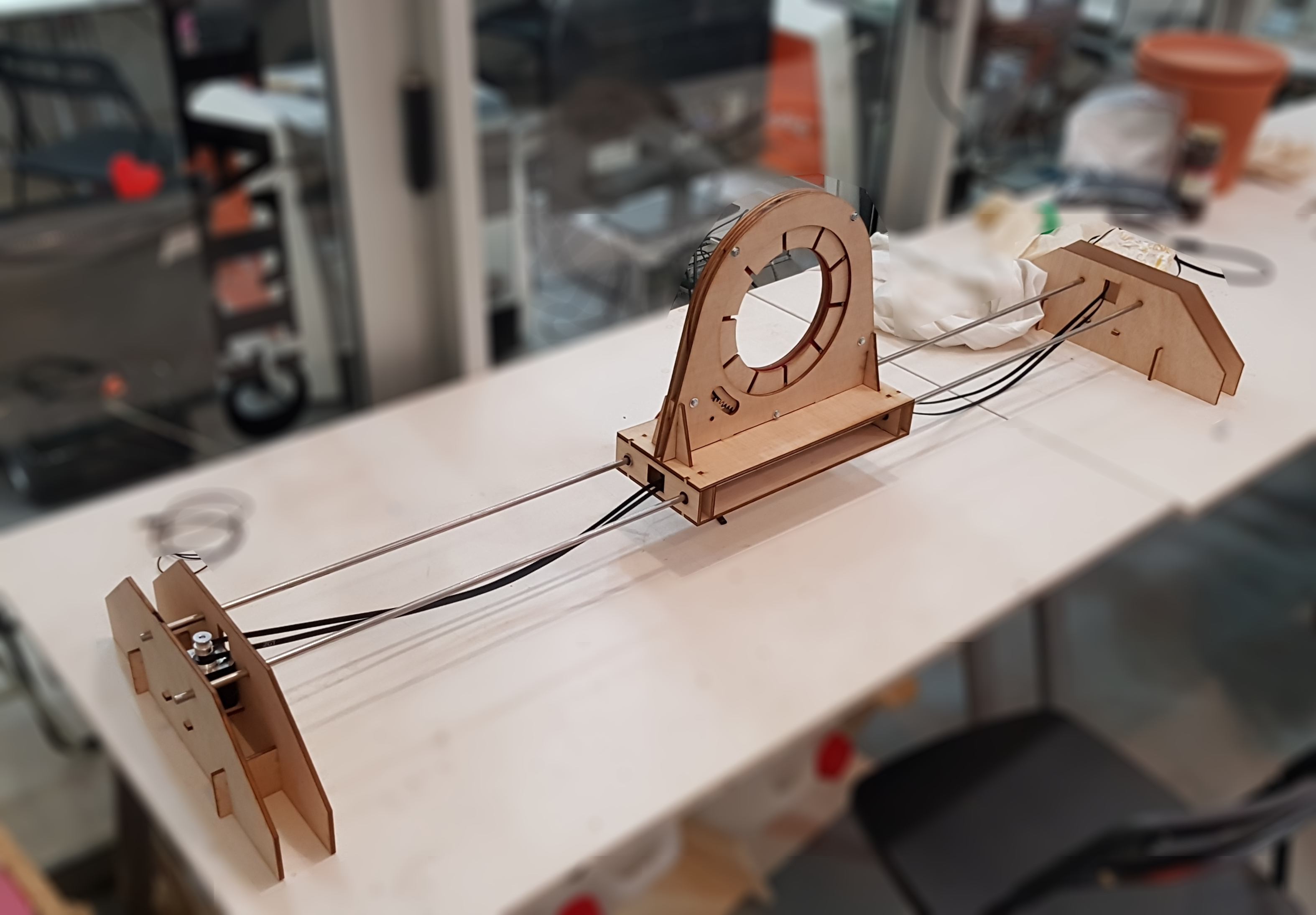
The belt needs to be tight, otherwise it will not grab the pulleys correctly. The code we upload is a loop driving the motor in one direction, then the other using the same number of steps.The platform goes from one side to the other repeatedly. To know how many steps it required to move from one side to the other, we noticed that 1000 steps made the platform move around 20%, so we kept increasing this number until it reached the other side. 4900 steps seem ok to move the platform along all the railings.
Below is the code written for the mechanical axis :
byte dirPin = 7;
byte stepPin = 6;
int steps = 4900;
int stepDelay = 2;
void setup() {
Serial.begin(9600);
Serial.println("Setup");
pinMode(dirPin, OUTPUT);
pinMode(stepPin, OUTPUT);
digitalWrite(dirPin, HIGH);
}
void loop() {
//Activar una direccion y fijar la velocidad con stepDelay
digitalWrite(dirPin, HIGH);
// Giramos 200 pulsos para hacer una vuelta completa
Serial.println("DIR1");
for(int n = 0; n < steps; n++) {
digitalWrite(stepPin, HIGH);
delayMicroseconds(stepDelay);
digitalWrite(stepPin, LOW);
delay(stepDelay);
//Serial.println(n);
}
delay(500);
//Cambiamos la direccion y aumentamos la velocidad
digitalWrite(dirPin, LOW);
//stepDelay = 2;
// Giramos 400 pulsos para hacer dos vueltas completas
Serial.println("DIR2");
for(int x = 0; x < steps; x++) {
digitalWrite(stepPin, HIGH);
delayMicroseconds(stepDelay);
digitalWrite(stepPin, LOW);
delay (stepDelay);
// Serial.println(x);
}
delay(500);
}
Play time!