Week 14: Mechanical design
on Assignments
This week we followed the mechanical design class. You can see video here.
For this assignment we decided to build a camera time-lapse dolly! :) This page is about the 1st part of the process in the group comprised by: Ilias Bartolini, Marta Bocos, André Pulcino, Óscar González
Concept
We would like the slider to have at least two controlled axis: (1) an horizontal rail and (2) and vertical camera rotation.
The camera would be placed on a flat plate and be supported by a conventional tripod head, attached to the plate by a screw. The plate would be sliding onto rails or tracks, and this would be moved by a stepper motor at the end of the rails. The rotation along the vertical axis would be done by a second servo motor, initially attached to the plate itself.
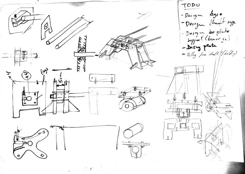
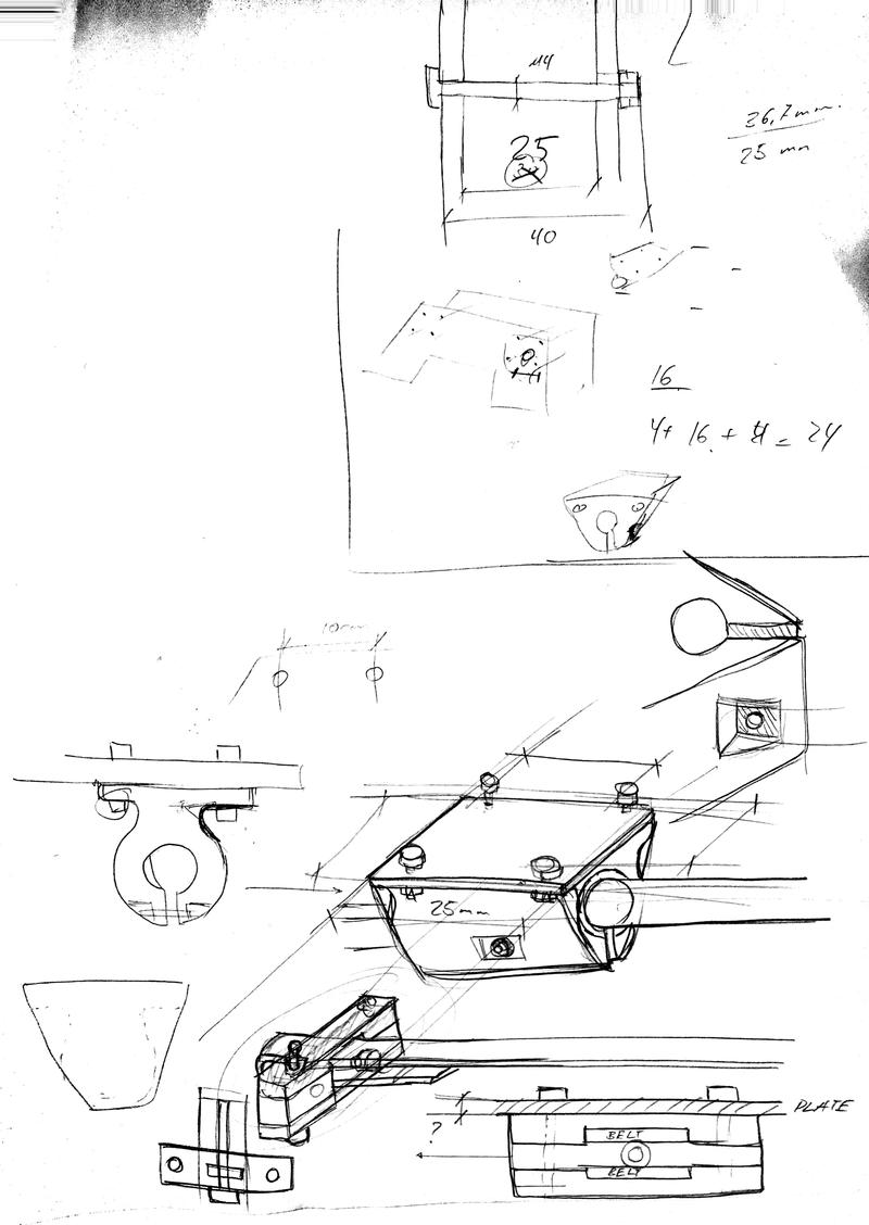
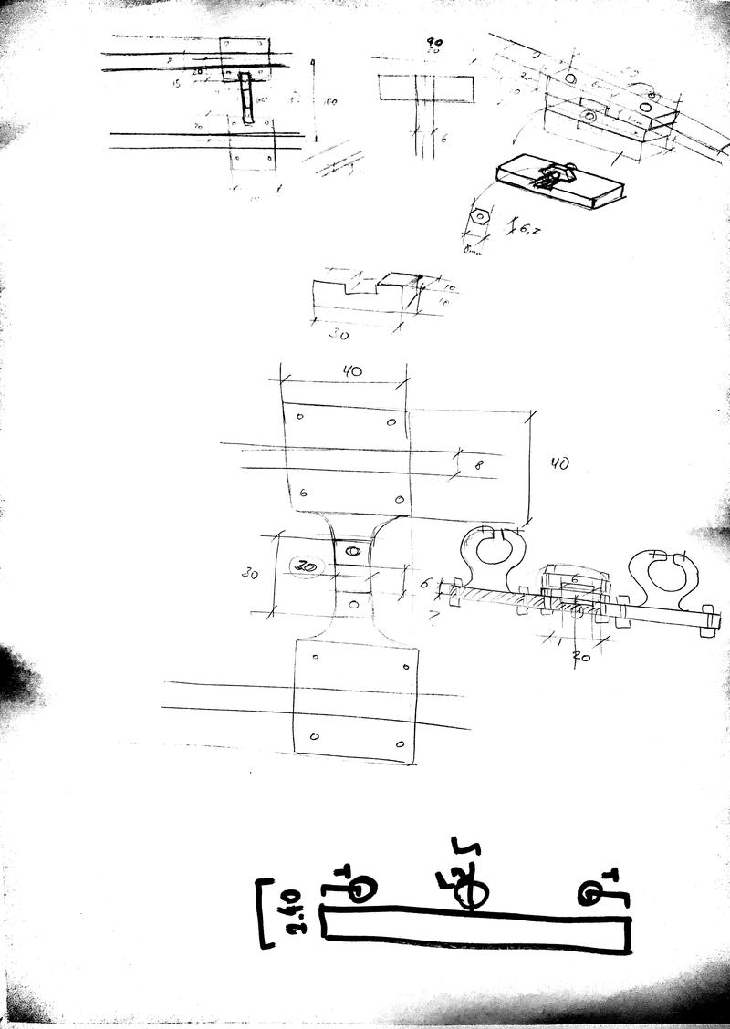
After looking at the various sample projects we started sketching together a solution. 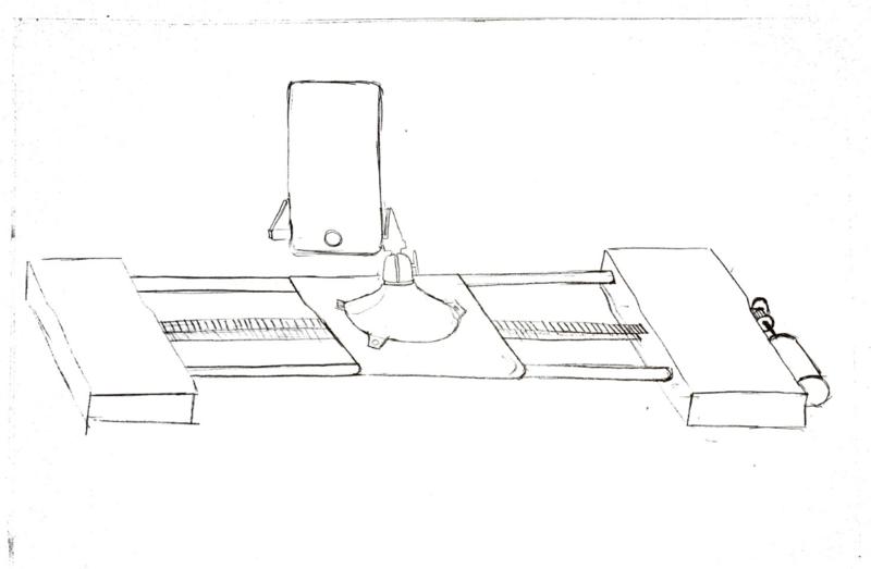
Below there is an initial list of components:
- Pipes: steel 8mm available at the lab
- Belt + pulleys: 6mm wide belt + pulleys
- End supports: to be laser cut with acrylic + 3D printed components
- Camera holder (PanaVise): to buy
- x1 Stepper motor (rails)
- x1 Servo motor (camera rotation)
Job Split
This week was a bit difficult for us in terms of planning because it happened to be a very busy / travelling week for all… Nevertheless, we managed to work altogether after some emails and arrangement.
We initially planned to execute it all via 3D printing, but as explained below, it would have ended up being a too long process and we decided to use both, laser and 3D printed parts. For this week, the initial concept was done by Andre, Marta and Ilias and the initial design in Fusion360 by Andre. Once things started rolling, the split was done as follows:
- Andre in charge of designing the 3D printed parts in Fusion360
- Ilias in charge of designing the laser cut parts
- Marta in charge of laser cutting them with Ilias
- Óscar in charge of the mechanical design of the pieces
The first week was then dedicated to manage some iterations of the mechanical design, with several trials of the laser cut parts and 3d printing. During this week, we learned that different fabrication processes can be joined to make a faster, more robust design, but that in some circumstances, the slowest process can delay things a bit (in this case 3D printing).
1st Iteration: CAD
Below we detail a first sketch of this model in CAD. These parts would have taken long time to print (more than 2 days to have all of them ready).
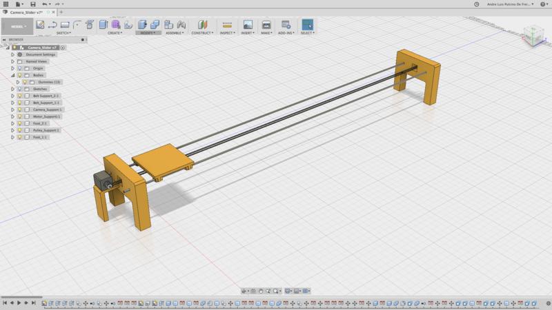
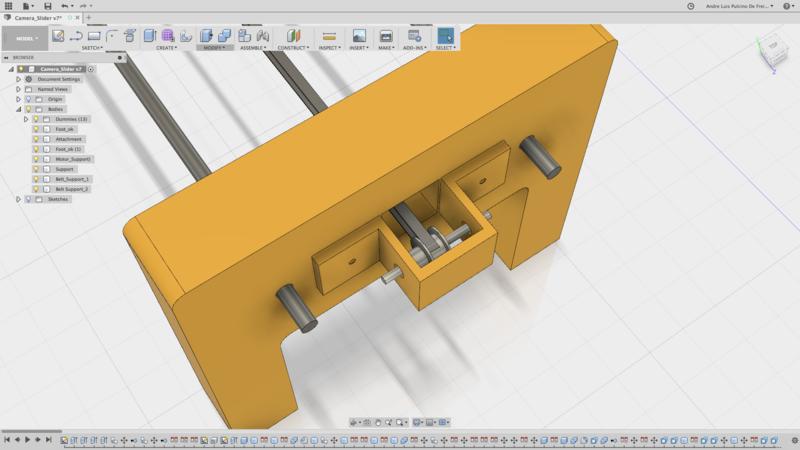
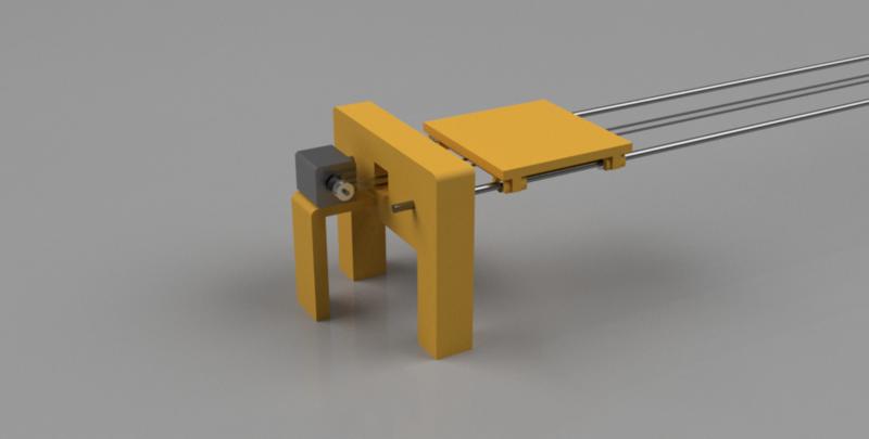
Therefore, we decided therefore to go back to pen and paper, and think how we could save some time.
2nd Iteration:
In this section, we will describe the final solution we went for. We took inspiration from the 3D printers mechanical design such as the HyperCube Evolution and some other RepRap solutions.
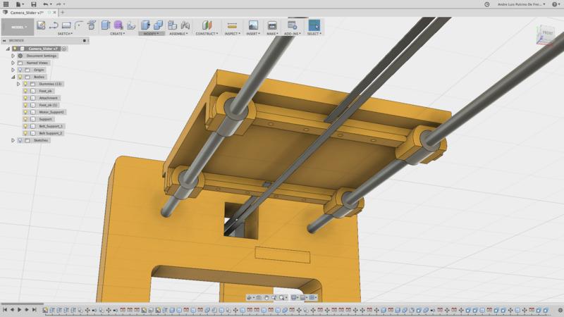
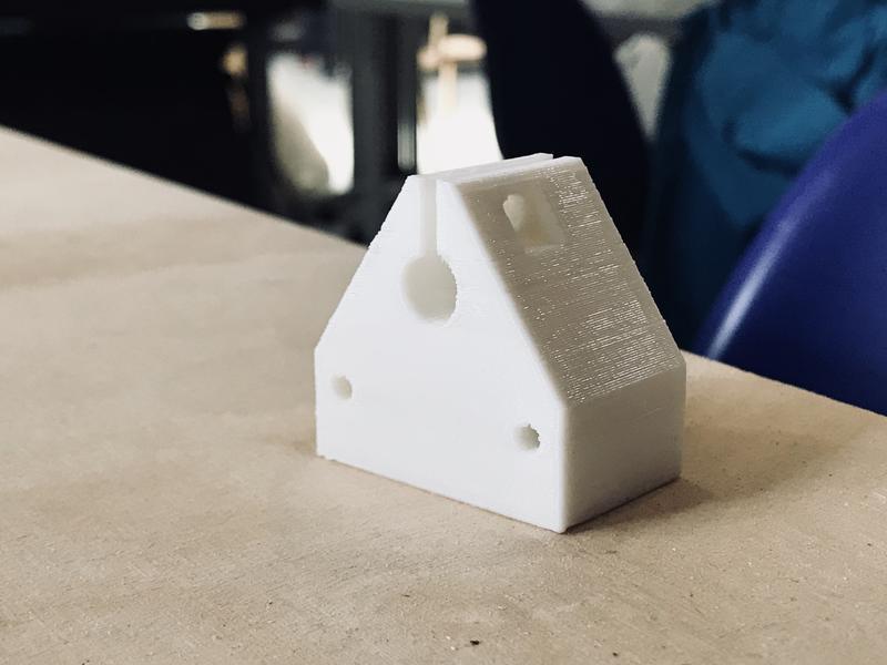
The shafts would be held by the rail ends with this solution, combining 5mm acrylic and 3D printing. We decided to use 3D printed parts to hold in the shafts, making use of the material’s flexibility to tighten in the shaft:
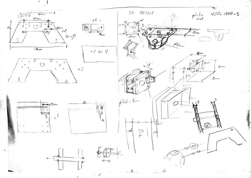
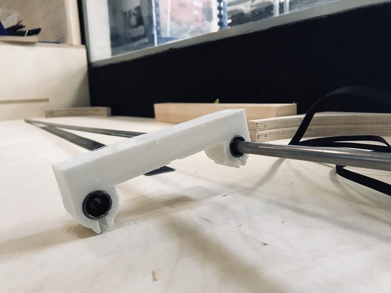
The plate would be held by a similar solution to this one. We will be using 4x linear bearings in two separate modules to be attached to the shaft.
Finally, the belt would be pulling from this type of solution, so that we guarantee the belt tightening:
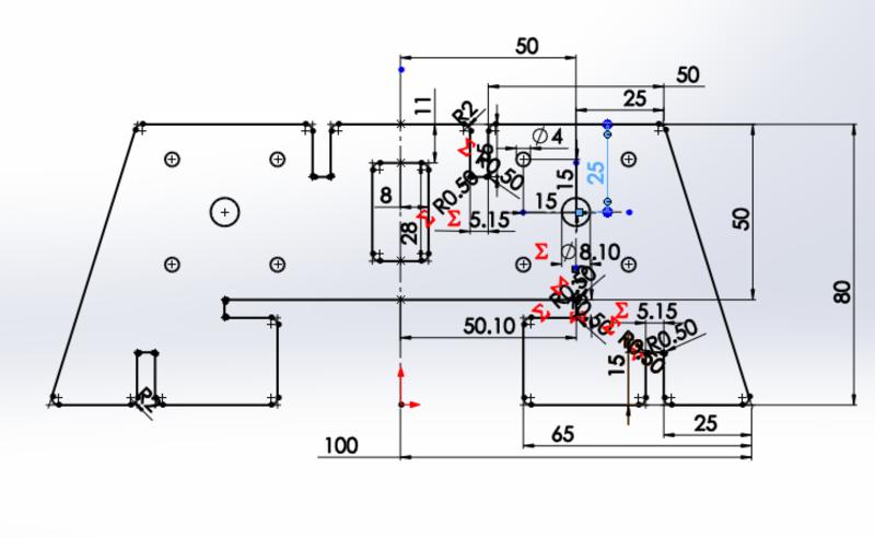
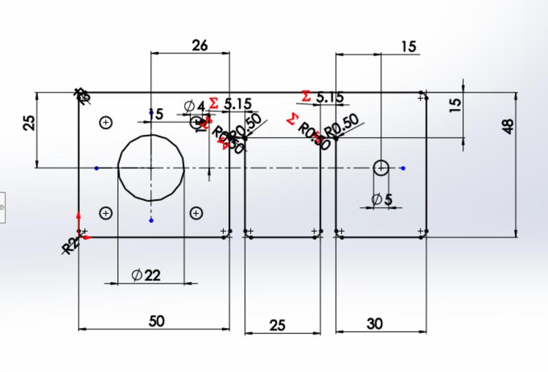
Laser cutting parts
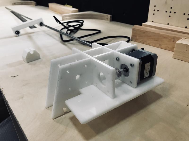
We quickly designed few new parts to build a quick prototype of the foot of our machine:

And assembled it in the afternoon to have an idea of how it would look like:
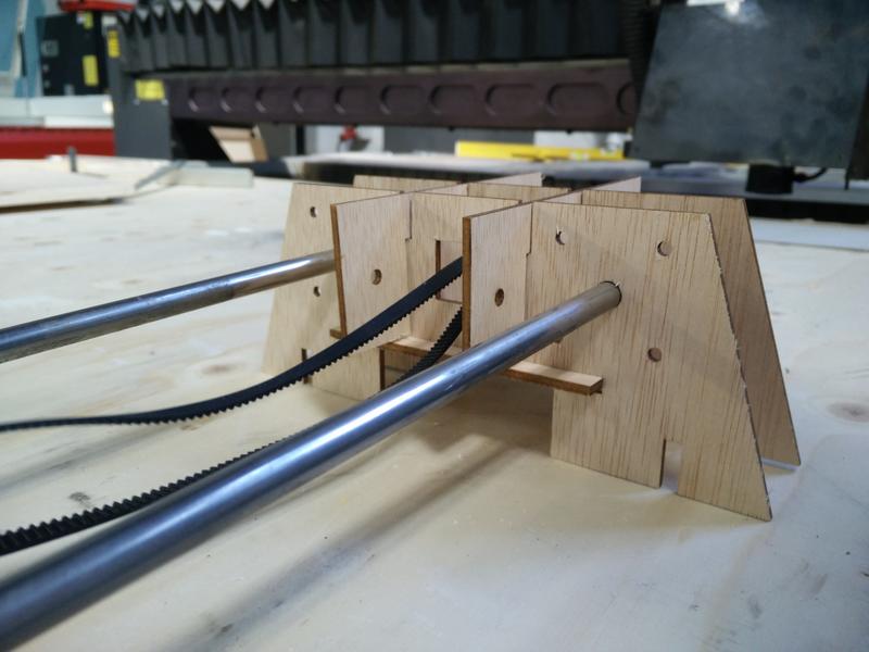
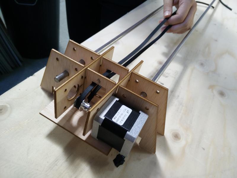
Quickly prototyping with laser cutting and plywood allowed us to quickly iterate on our design.
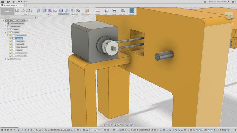
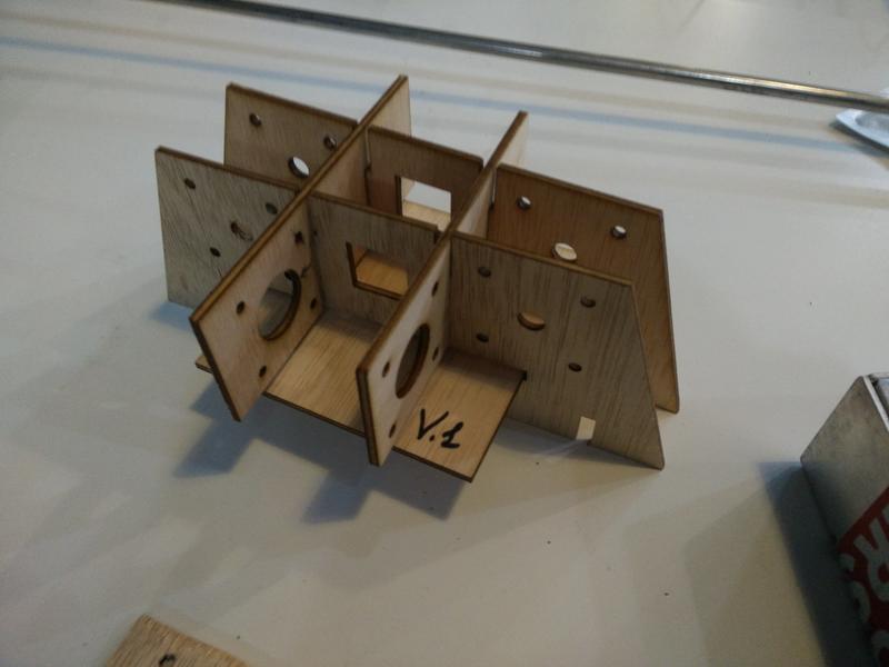
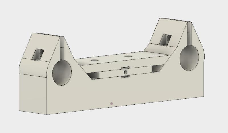
First we fixed the motor positioning, the screws holes tolerances, chamfers and dogbones: 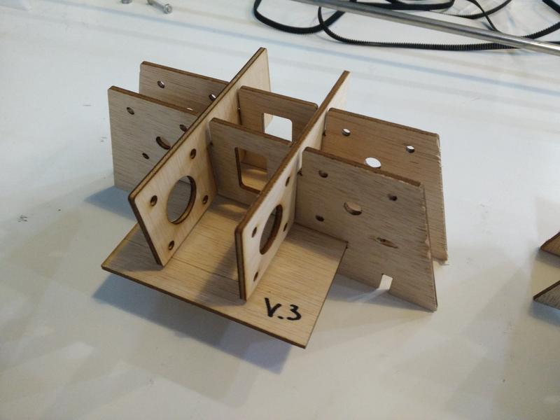
In a following iteration we increased the support plate width for the motor, added lateral-bottom pressfit parts, increased the dogbones sizes: 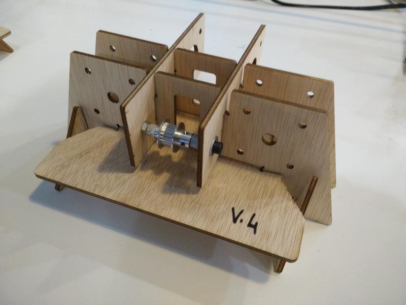
Finally we fixed the belt hole and a mistake between the bottom support plate width and the new lateral-bottom pressfit parts: 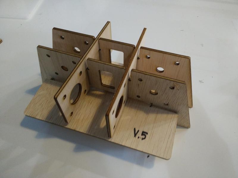
The camera support plate also went through a couple of iterations while we designed our 3D printed parts to attach to the pipes and belt: 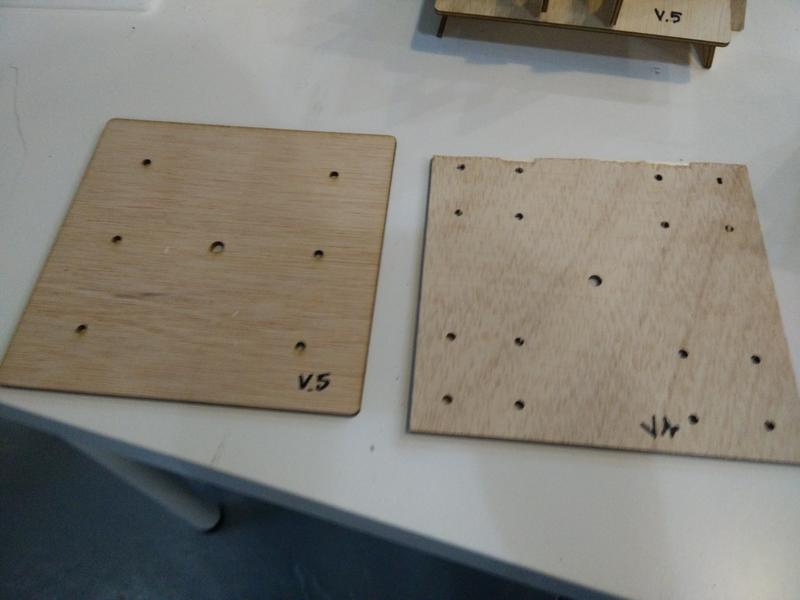
At this point we were ready for cutting the prototype in acrylic material.
Download Sources (.zip archive)
Characterising acrylic material
We started testing the following setting for acrylic based on other students experience
| Power | Speed | PPI/Hz |
|---|---|---|
| 100 | 0.6 | 2500 |
After few test we ended with
| Power | Speed | PPI/Hz |
|---|---|---|
| 100 | 0.45 | 70000 |
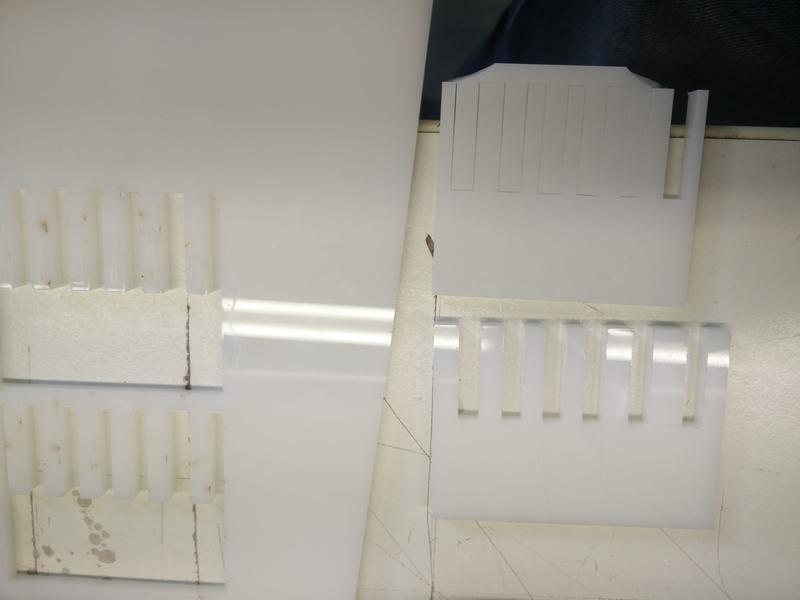
Then we checked the kerf for the material.
We found that the slots between 5.1mm and 5.2mm are the one with the best press fit. We started designing our model with a kerf between 0.05mm and 0.1mm: that is 0.075mm
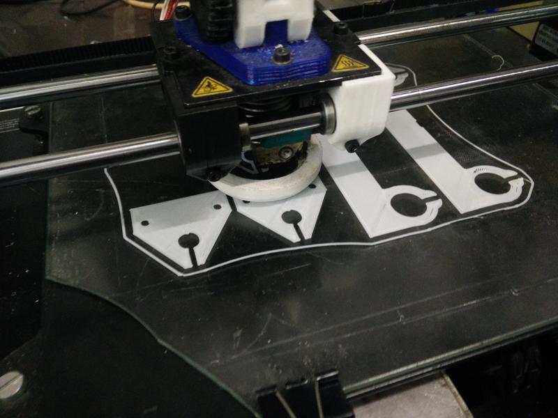
3D printing parts
We will be using the Makerbot 3D printer. The settings used for these parts are the following:
- Material: white PLA
- Infill: 20% - Cubic
- Layer height: 0.15mm
- Initial layer height: 0.3mm
- Line width: 0.4mm
- Wall line count: 3mm
- Printing temperature: 205degC
- Filament: 1.75mm
- Flow 100%
- Travel Speed: 120mm/s
- Print speed: 60mm/s
- Retraction: 6.5mm
Below we detail the 3D printing components we will be using:
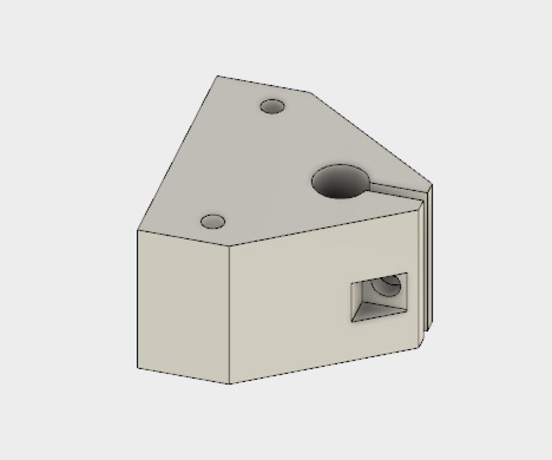
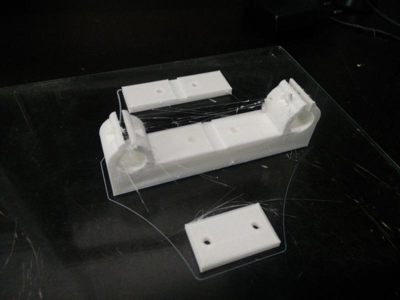
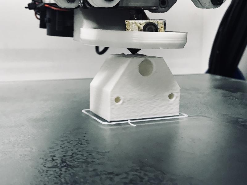
Shaft support:
Bearing and belt support for the moving plate: 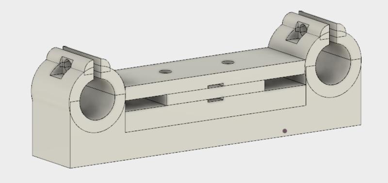
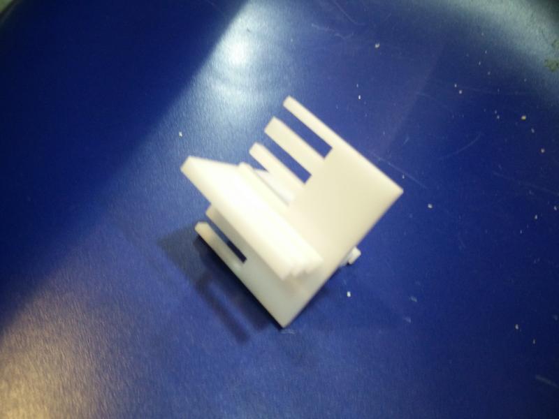
These were all printed with white PLA, with a very painful adjustment process to make it print properly. We also tested which was the best printing direction in order to best use the mechanical properties of the material.
Below some results:
Download Sources (.zip archive)
Putting it all together
Pulleys, screws, etc.
Lessons learned
- Visualising things early even with simple sketches gets more important when more people are working together as a team;
- For the purpose of the first few prototypes with the laser cutter we could have easily used cardboard instead of plywood;
- 3D printing process get a lot slower with the volume of the pieces to print and the probability of failure makes it less valuable for quick iterative prototyping;
- Mechanical properties of 3D printed material relies upon highly on layer height, printing direction and positioning of the piece on the printing plate;
- Common mechanical considerations like fillets and avoiding stress concentrations should be taken even more into account with 3D printing;
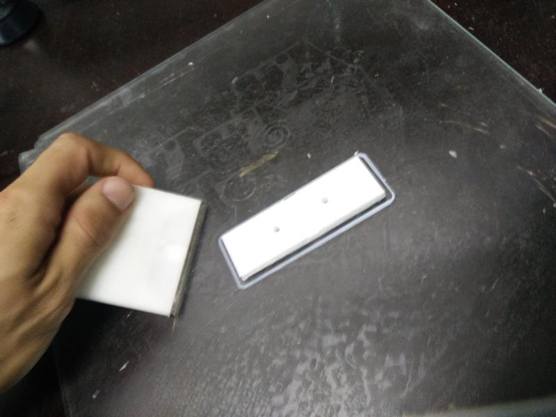
- The 3D parts we have printed have considerably shrunk in some of their holes, probably due to the melting and settlement of the PLA. It made some hole tighter than we expected, which helped in some cases to create more tension and stability. But, as a rule of thumb, 0.5mm of tolerance have been added to the planned holes.
Next steps
- Easy to assemble platform: the clamps opening at the bottom of the platform could be wide enough to allow it to be easily detachable: currently we need to remove the foot.
- Improve the belt tensioning mechanism with a screw & bolt that allow an easy regulation.
- Check press-fit tolerances and design a way to block the bottom layer of the feet.
- Test a different solution with rails instead of pipes to limit the bending of the structure.