We initially learned how to use a stepper motor and make it move as wished with an Arduino CNC shield. For this, Ilias’s job started the motors and made them move for the first time.
Later on, we all colaborated as follows:
Marta and Ilias to set up the motors and fit up the endstops in place
Óscar and Andre to program the board and define the interaction with the endstops
Using a stepper motor
First simple example we took ad Arduino CNC shield with a DRV8825 stepper motor driver.
A good introductory guide to have our example working is this.
Documentation for the DRV8825 features and pinout is available here. Documentation for the Arduino CNC shiled is available here.
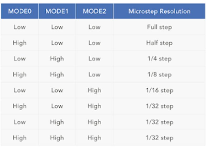
The DRV8825 driver allow for various step resolution which can be configured via the jumpers on the CNC shield:
We picked the higher resolution and then tested with the sample code from the tutorial modified as below:
#define EN        8
//Direction pin
#define X_DIR     5
//Step pin
#define X_STP     2
//DRV8825
int delayTime=3200; //Delay between each pause (uS)
int steps=6400;// Steps to move

void move(boolean dir, byte dirPin, byte stepperPin, int steps)
{
  digitalWrite(dirPin, dir);
  delay(100);
  for (int i = 0; i < steps; i++) {
    digitalWrite(stepperPin, HIGH);
    delayMicroseconds(delayTime);
    digitalWrite(stepperPin, LOW);
    delayMicroseconds(delayTime);
  }
}

void setup(){
  pinMode(X_DIR, OUTPUT); pinMode(X_STP, OUTPUT);
  pinMode(EN, OUTPUT);
  digitalWrite(EN, LOW);
}

void loop(){
  move(false, X_DIR, X_STP, steps); //X, Clockwise
  delay(1000);
  move(true, X_DIR, X_STP, steps); //X, Counterclockwise
  delay(1000);
Here is the result.
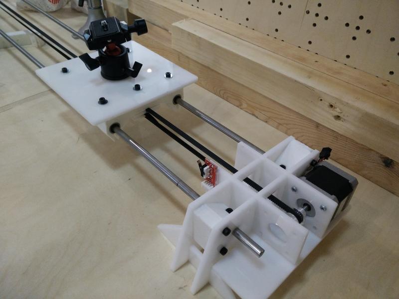
Testing the motor on our machine
First of all we had to register the torque/current limit supplied to the motor by the stepper driver. The DRV8825 has a potentiometer which lets you regulate this setting. Later on I found this useful guide for this process.
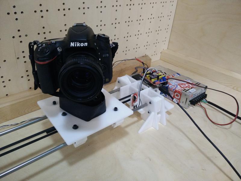
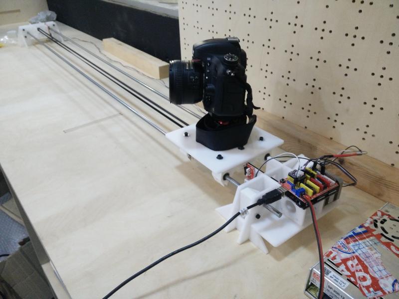
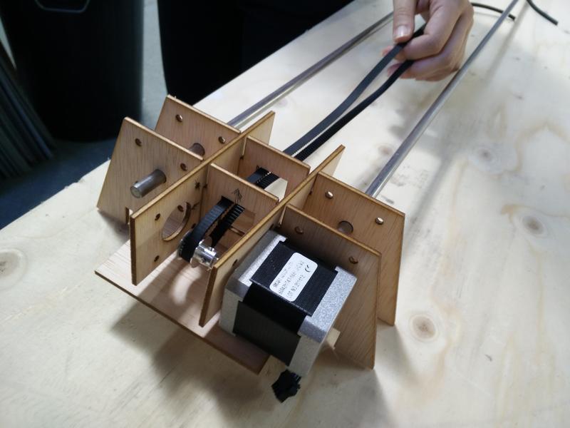
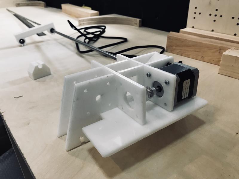
After registering the current limit here is the functioning prototype assembled on our machine.
A little bit of adjustment was necessary to find the correct steps frequency and belt tension to avoid vibrations but still have a slow movement of the platform.
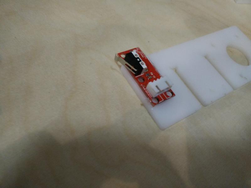
Adding endstops
We started thiking at different ways to add the endstops to the dolly structure and ended up with a simple glue solution :)
Here is the endstop assembled with the machine.
Firmware
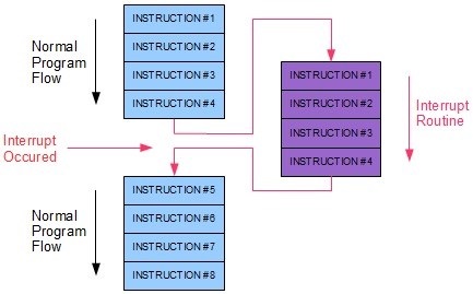
In terms of firmware, we had a look at the possibilities of using the end-stops with an ISR (Interrupt Service Routine), in order to do it the neat way:
We will be using an Arduino Uno with an ATMEGA328P-PU, which has a wide range of digital pins to be used. However, not all the pins can be used for an Interrupt with the attachInterrupt() function as stated in this link, and the hat we are using is definitively not using only those (2 and 3). Therefore, we would need to use the ISR in a different way. One good documentation about it is the one from Nick Gammon’s. From his site, a brief description of interrupts would define them as a way to let you respond to “external” events while doing something else.
For the ATMEGA328, below there is a list of available interrupts, in order of priority:
 1  Reset
 2  External Interrupt Request 0  (pin D2)          (INT0_vect)
 3  External Interrupt Request 1  (pin D3)          (INT1_vect)
 4  Pin Change Interrupt Request 0 (pins D8 to D13) (PCINT0_vect)
 5  Pin Change Interrupt Request 1 (pins A0 to A5)  (PCINT1_vect)
 6  Pin Change Interrupt Request 2 (pins D0 to D7)  (PCINT2_vect)
 7  Watchdog Time-out Interrupt                     (WDT_vect)
 8  Timer/Counter2 Compare Match A                  (TIMER2_COMPA_vect)
 9  Timer/Counter2 Compare Match B                  (TIMER2_COMPB_vect)
10  Timer/Counter2 Overflow                         (TIMER2_OVF_vect)
11  Timer/Counter1 Capture Event                    (TIMER1_CAPT_vect)
12  Timer/Counter1 Compare Match A                  (TIMER1_COMPA_vect)
13  Timer/Counter1 Compare Match B                  (TIMER1_COMPB_vect)
14  Timer/Counter1 Overflow                         (TIMER1_OVF_vect)
15  Timer/Counter0 Compare Match A                  (TIMER0_COMPA_vect)
16  Timer/Counter0 Compare Match B                  (TIMER0_COMPB_vect)
17  Timer/Counter0 Overflow                         (TIMER0_OVF_vect)
18  SPI Serial Transfer Complete                    (SPI_STC_vect)
19  USART Rx Complete                               (USART_RX_vect)
20  USART, Data Register Empty                      (USART_UDRE_vect)
21  USART, Tx Complete                              (USART_TX_vect)
22  ADC Conversion Complete                         (ADC_vect)
23  EEPROM Ready                                    (EE_READY_vect)
24  Analog Comparator                               (ANALOG_COMP_vect)
25  2-wire Serial Interface  (I2C)                  (TWI_vect)
26  Store Program Memory Ready                      (SPM_READY_vect)
The D2 and D3 pins are the ones mentioned in the Arduino documentation. However, we will be using the pins D8 to D13 with the PCINT0_vect services. For that we will have to write our own strategy, and to make it right we used the one from grbl, first by defining an interrupt function on the PCINT0_vect pins:
#define LIMIT_INT_vect   PCINT0_vect

ISR(LIMIT_INT_vect) // DEFAULT: Limit pin change interrupt process.
{

uint8_t state = limits_get_state();
  switch (state) {
      case 1:
        dir = false;
        break;
      case 0:
        dir = true;
        break;
  }
}
This function checks the status of the pins whenever triggered via the function limits_get_state():
uint8_t limits_get_state()
{
  uint8_t limit_state = 2;

  if (digitalRead(9)==HIGH && digitalRead(10)==LOW){
    limit_state = 1;
  }
  if (digitalRead(9) == LOW && digitalRead(10)==HIGH) {
    limit_state = 0;
  }

  // The first time we home, we don't do it again
  if (!home){
    home = true;
  }

  return(limit_state);
}
This surely can be done in a much more efficient way, but it serves our purposes: we are checking every time an ISR is coming on the digital pins of PCINT0vect which one of the two are HIGH, either the pin 9 or the pin 10. In case of not having done the _homing yet, we set the home flag to true, to change the movement settings from fast to slow. The variable containing which direction is the motor turning is changed accordingly and is sent in the main loop:
And here a sample video of our Sloth time-lapse recording!!! \o/ \o/
Lessons learned
How to drive a stepper motor! :)
When we built our final structure, we made assumptions about the motor and drive mechanism: ideally we should be iterating on the mechanical structure once we learned about the components used.
Driving a single motor is quite easy in code and we do not require a more complex CNC shield for this.
Next steps
Add a speed control potentiometer.
Optimize for battery powered components.
Try smaller 5V stepper motor with gearing: eg. this.
Try wiring the stepper driver without using the CNC shield.
Design a better enclosure and wiring of the electronic parts.
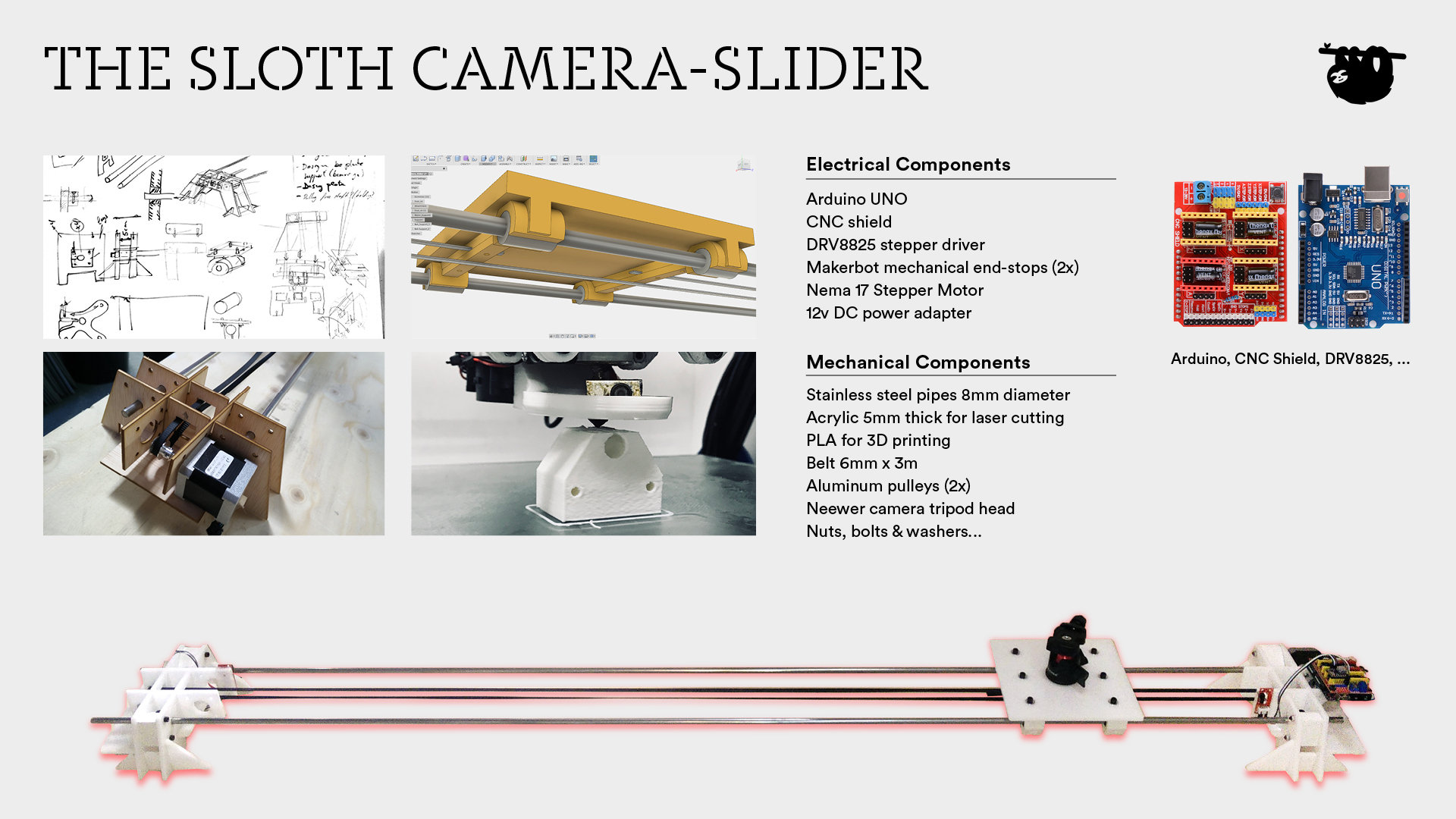
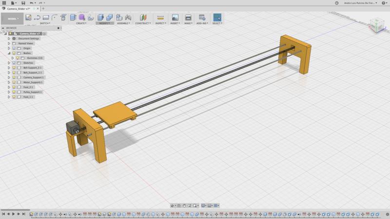
We would like the slider to have at least two controlled axis: (1) an horizontal rail and (2) and vertical camera rotation.
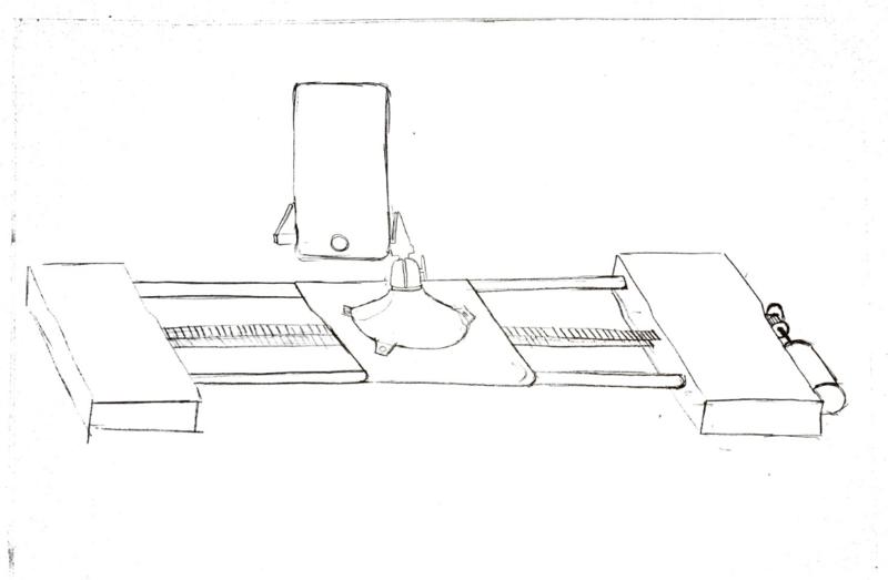
The camera would be placed on a flat plate and be supported by a conventional tripod head, attached to the plate by a screw. The plate would be sliding onto rails or tracks, and this would be moved by a stepper motor at the end of the rails. The rotation along the vertical axis would be done by a second servo motor, initially attached to the plate itself.
After looking at the various sample projects we started sketching together a solution.
Below there is an initial list of components:
Pipes: steel 8mm available at the lab
Belt + pulleys: 6mm wide belt + pulleys
End supports: to be laser cut with acrylic + 3D printed components
Camera holder (PanaVise): to buy
x1 Stepper motor (rails)
x1 Servo motor (camera rotation)
Job Split
This week was a bit difficult for us in terms of planning because it happened to be a very busy / travelling week for all… Nevertheless, we managed to work altogether after some emails and arrangement.
We initially planned to execute it all via 3D printing, but as explained below, it would have ended up being a too long process and we decided to use both, laser and 3D printed parts. For this week, the initial concept was done by Andre, Marta and Ilias and the initial design in Fusion360 by Andre. Once things started rolling, the split was done as follows:
Andre in charge of designing the 3D printed parts in Fusion360
Ilias in charge of designing the laser cut parts
Marta in charge of laser cutting them with Ilias
Óscar in charge of the mechanical design of the pieces
The first week was then dedicated to manage some iterations of the mechanical design, with several trials of the laser cut parts and 3d printing. During this week, we learned that different fabrication processes can be joined to make a faster, more robust design, but that in some circumstances, the slowest process can delay things a bit (in this case 3D printing).
1st Iteration: CAD
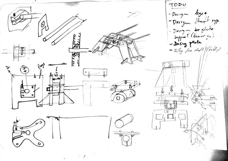
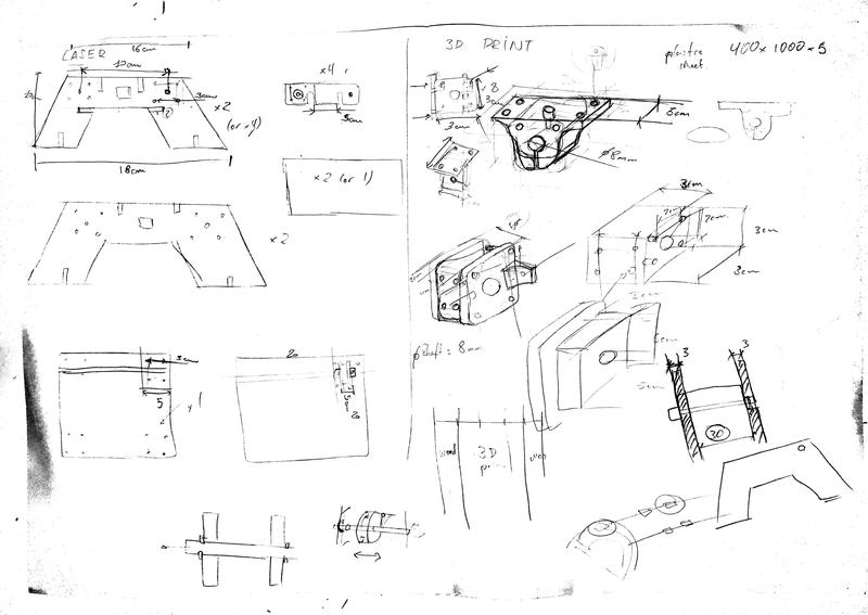
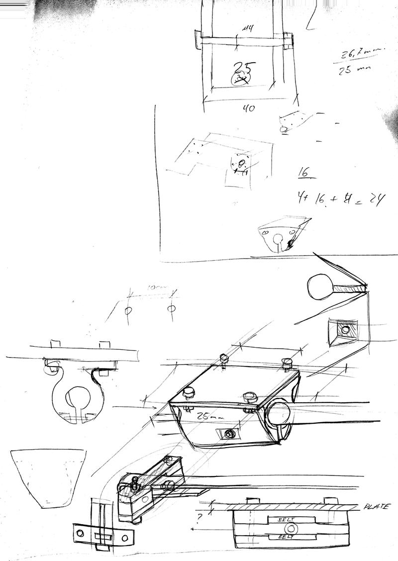
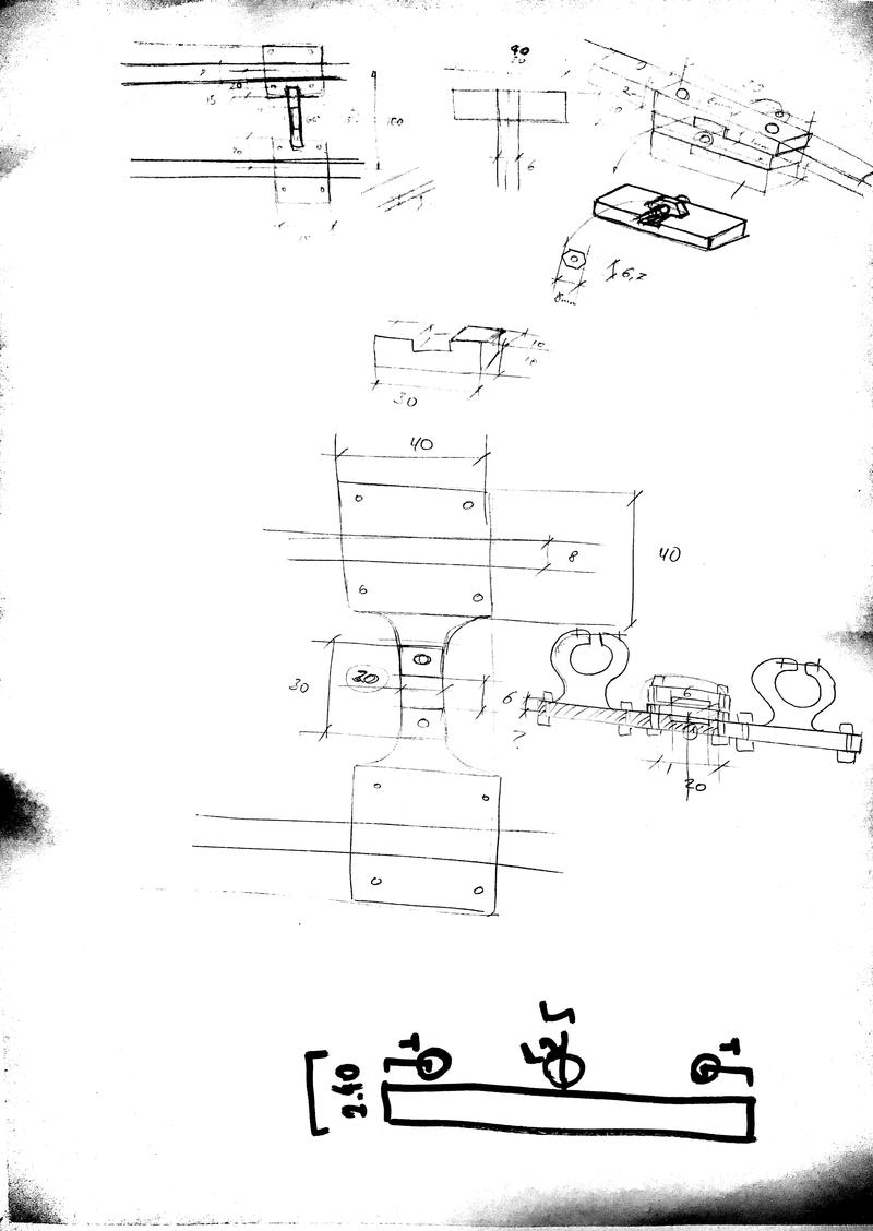
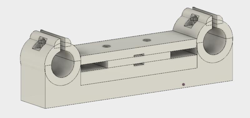
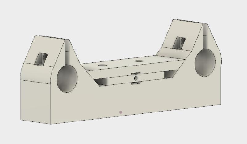
Below we detail a first sketch of this model in CAD. These parts would have taken long time to print (more than 2 days to have all of them ready).
Therefore, we decided therefore to go back to pen and paper, and think how we could save some time.
2nd Iteration:
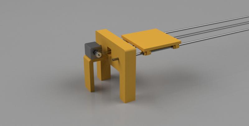
In this section, we will describe the final solution we went for. We took inspiration from the 3D printers mechanical design such as the HyperCube Evolution and some other RepRap solutions.
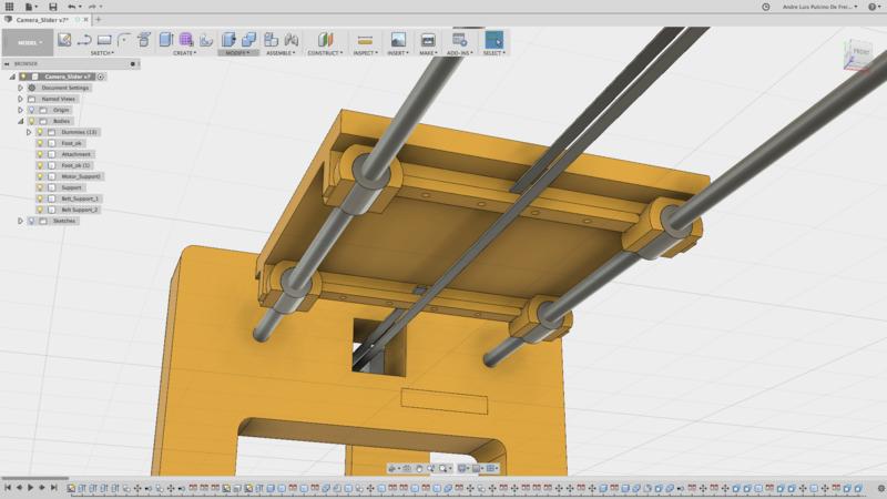
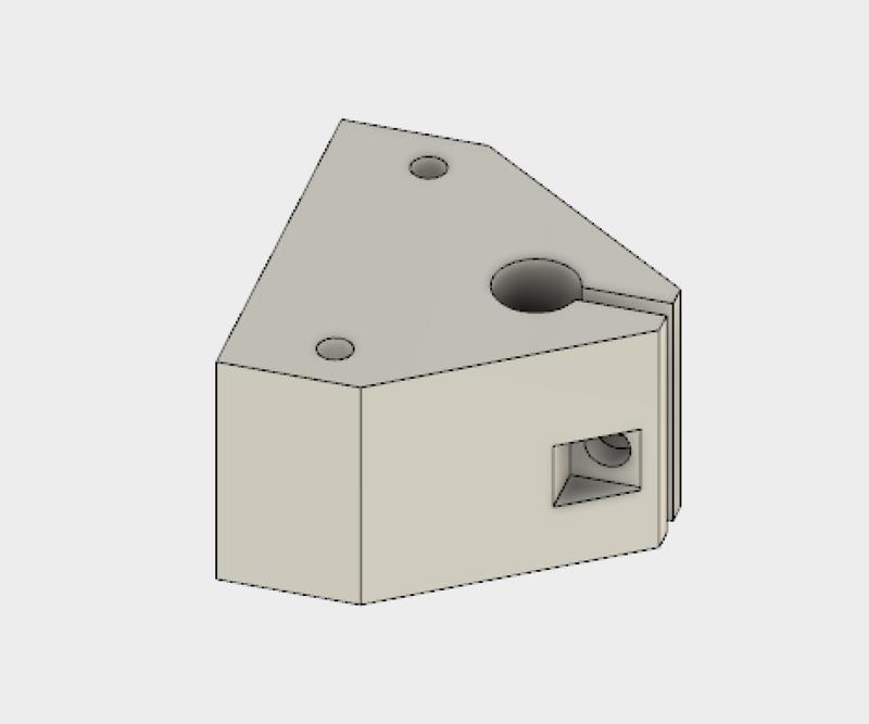
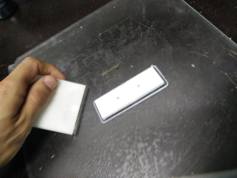
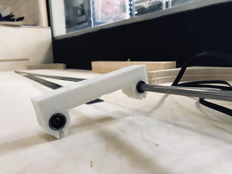
The shafts would be held by the rail ends with this solution, combining 5mm acrylic and 3D printing. We decided to use 3D printed parts to hold in the shafts, making use of the material’s flexibility to tighten in the shaft:
The plate would be held by a similar solution to this one. We will be using 4x linear bearings in two separate modules to be attached to the shaft.
Finally, the belt would be pulling from this type of solution, so that we guarantee the belt tightening:
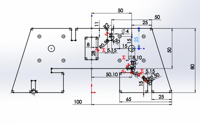
Laser cutting parts
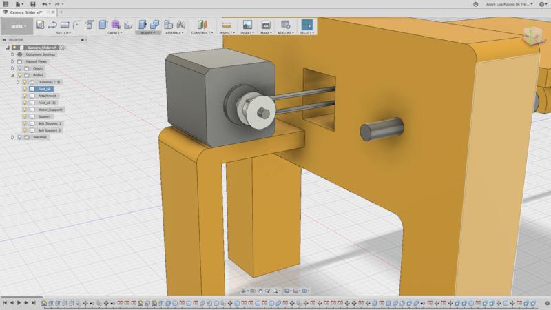
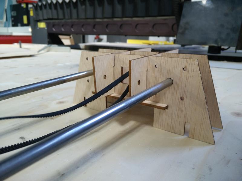
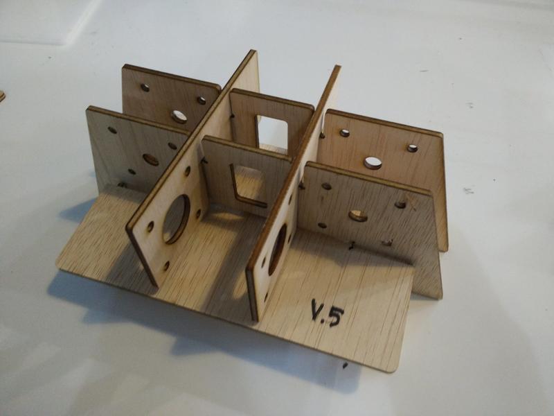
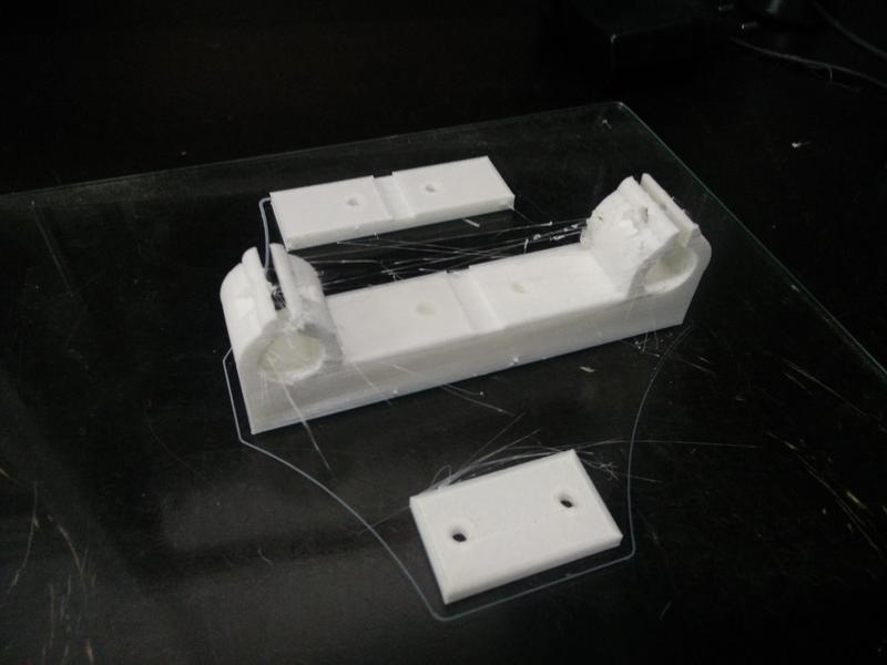
We quickly designed few new parts to build a quick prototype of the foot of our machine:
And assembled it in the afternoon to have an idea of how it would look like:
Quickly prototyping with laser cutting and plywood allowed us to quickly iterate on our design.
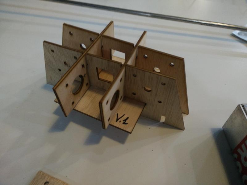
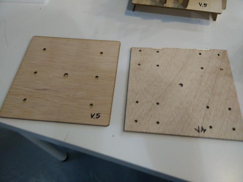
First we fixed the motor positioning, the screws holes tolerances, chamfers and dogbones:
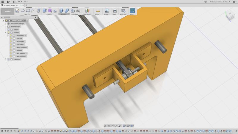
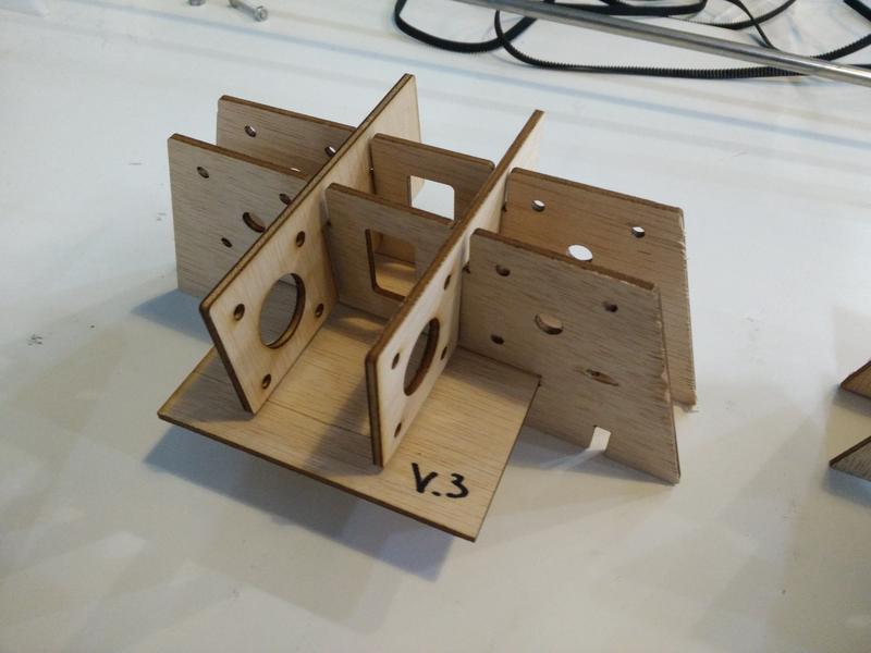
In a following iteration we increased the support plate width for the motor, added lateral-bottom pressfit parts, increased the dogbones sizes:
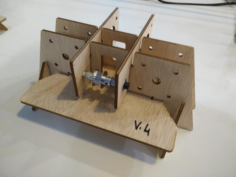
Finally we fixed the belt hole and a mistake between the bottom support plate width and the new lateral-bottom pressfit parts:
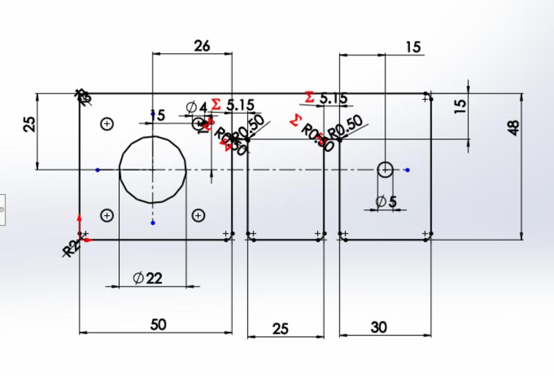
The camera support plate also went through a couple of iterations while we designed our 3D printed parts to attach to the pipes and belt:
At this point we were ready for cutting the prototype in acrylic material.
We started testing the following setting for acrylic based on other students experience
Power
Speed
PPI/Hz
100
0.6
2500
After few test we ended with
Power
Speed
PPI/Hz
100
0.45
70000
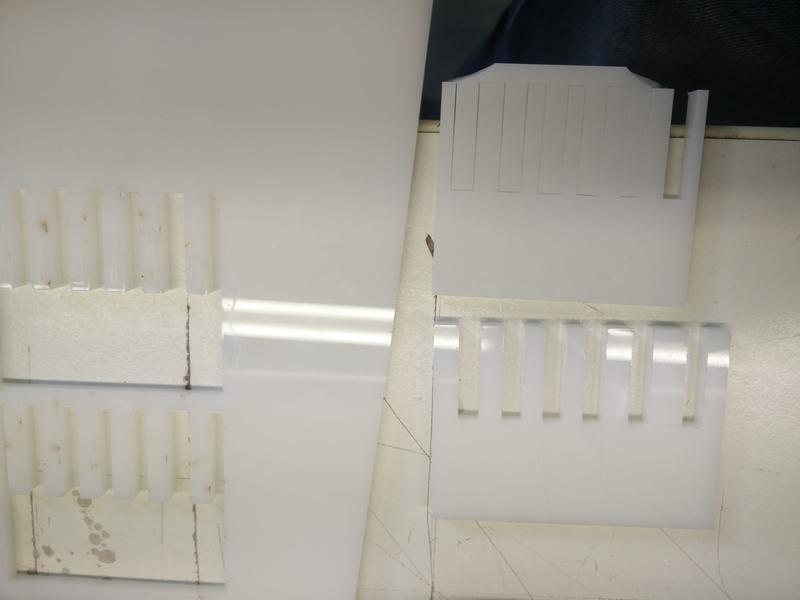
Then we checked the kerf for the material.
We found that the slots between 5.1mm and 5.2mm are the one with the best press fit. We started designing our model with a kerf between 0.05mm and 0.1mm: that is 0.075mm
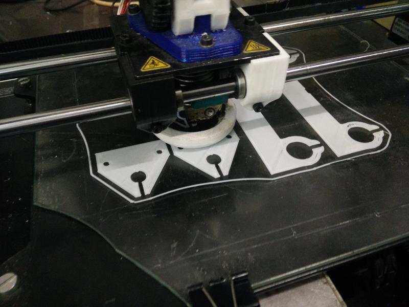
3D printing parts
We will be using the Makerbot 3D printer. The settings used for these parts are the following:
Material: white PLA
Infill: 20% - Cubic
Layer height: 0.15mm
Initial layer height: 0.3mm
Line width: 0.4mm
Wall line count: 3mm
Printing temperature: 205degC
Filament: 1.75mm
Flow 100%
Travel Speed: 120mm/s
Print speed: 60mm/s
Retraction: 6.5mm
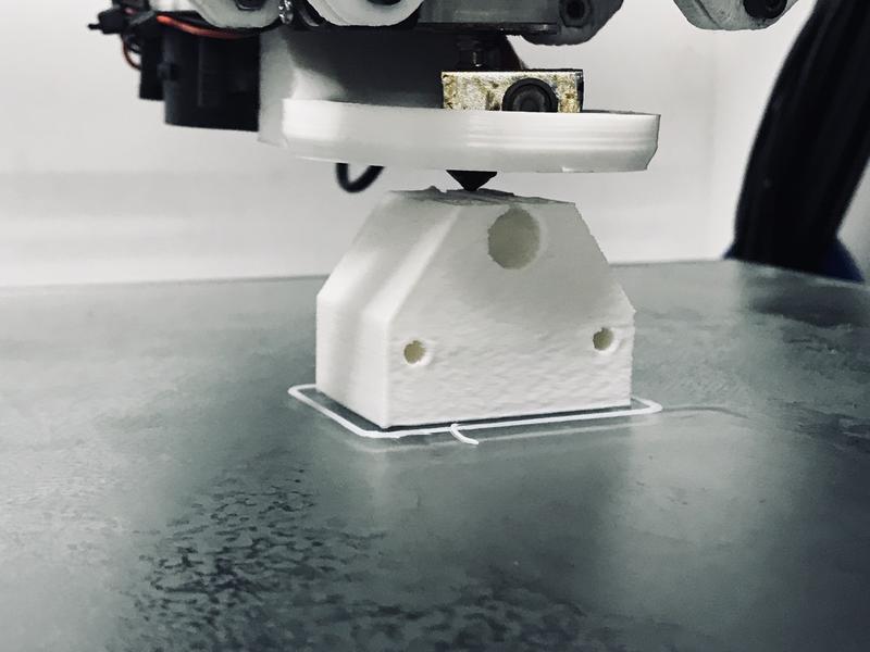
Below we detail the 3D printing components we will be using:
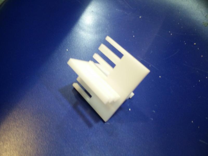
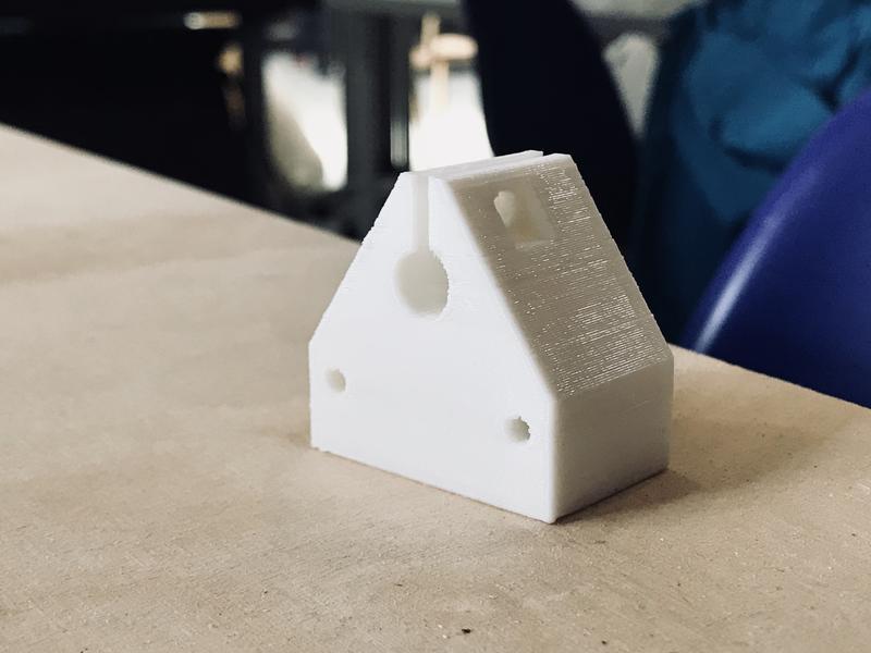
Shaft support:
Bearing and belt support for the moving plate:
These were all printed with white PLA, with a very painful adjustment process to make it print properly. We also tested which was the best printing direction in order to best use the mechanical properties of the material.
Visualising things early even with simple sketches gets more important when more people are working together as a team;
For the purpose of the first few prototypes with the laser cutter we could have easily used cardboard instead of plywood;
3D printing process get a lot slower with the volume of the pieces to print and the probability of failure makes it less valuable for quick iterative prototyping;
Mechanical properties of 3D printed material relies upon highly on layer height, printing direction and positioning of the piece on the printing plate;
Common mechanical considerations like fillets and avoiding stress concentrations should be taken even more into account with 3D printing;
The 3D parts we have printed have considerably shrunk in some of their holes, probably due to the melting and settlement of the PLA. It made some hole tighter than we expected, which helped in some cases to create more tension and stability. But, as a rule of thumb, 0.5mm of tolerance have been added to the planned holes.
Next steps
Easy to assemble platform: the clamps opening at the bottom of the platform could be wide enough to allow it to be easily detachable: currently we need to remove the foot.
Improve the belt tensioning mechanism with a screw & bolt that allow an easy regulation.
Check press-fit tolerances and design a way to block the bottom layer of the feet.
Test a different solution with rails instead of pipes to limit the bending of the structure.