Week 15: Machine design
on Assignments
During this week we followed the machine design class. You can see video here.
For this assignment we added a control system to our camera time-lapse dolly! :)
This page is about the 1st part of the process in the group comprised by: Ilias Bartolini, Marta Bocos, André Pulcino, Óscar González
- Job Split
- Using a stepper motor
- Testing the motor on our machine
- Adding endstops
- Final result
- Lessons learned
- Next steps
Job Split
We initially learned how to use a stepper motor and make it move as wished with an Arduino CNC shield. For this, Ilias’s job started the motors and made them move for the first time.
Later on, we all colaborated as follows:
- Marta and Ilias to set up the motors and fit up the endstops in place
- Óscar and Andre to program the board and define the interaction with the endstops
Using a stepper motor
First simple example we took ad Arduino CNC shield with a DRV8825 stepper motor driver.
A good introductory guide to have our example working is this.
Documentation for the DRV8825 features and pinout is available here.
Documentation for the Arduino CNC shiled is available here.
The DRV8825 driver allow for various step resolution which can be configured via the jumpers on the CNC shield: 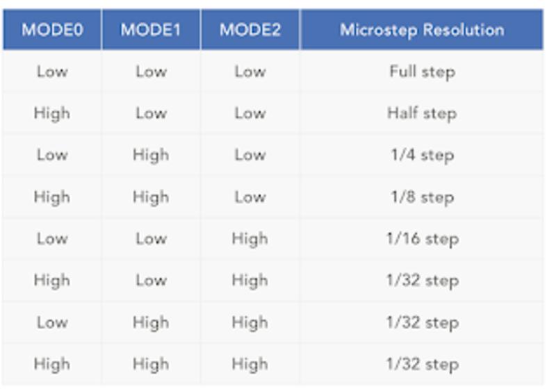
We picked the higher resolution and then tested with the sample code from the tutorial modified as below:
#define EN        8
//Direction pin
#define X_DIR     5
//Step pin
#define X_STP     2
//DRV8825
int delayTime=3200; //Delay between each pause (uS)
int steps=6400;// Steps to move

void move(boolean dir, byte dirPin, byte stepperPin, int steps)
{
  digitalWrite(dirPin, dir);
  delay(100);
  for (int i = 0; i < steps; i++) {
    digitalWrite(stepperPin, HIGH);
    delayMicroseconds(delayTime);
    digitalWrite(stepperPin, LOW);
    delayMicroseconds(delayTime);
  }
}

void setup(){
  pinMode(X_DIR, OUTPUT); pinMode(X_STP, OUTPUT);
  pinMode(EN, OUTPUT);
  digitalWrite(EN, LOW);
}

void loop(){
  move(false, X_DIR, X_STP, steps); //X, Clockwise
  delay(1000);
  move(true, X_DIR, X_STP, steps); //X, Counterclockwise
  delay(1000);
Here is the result.
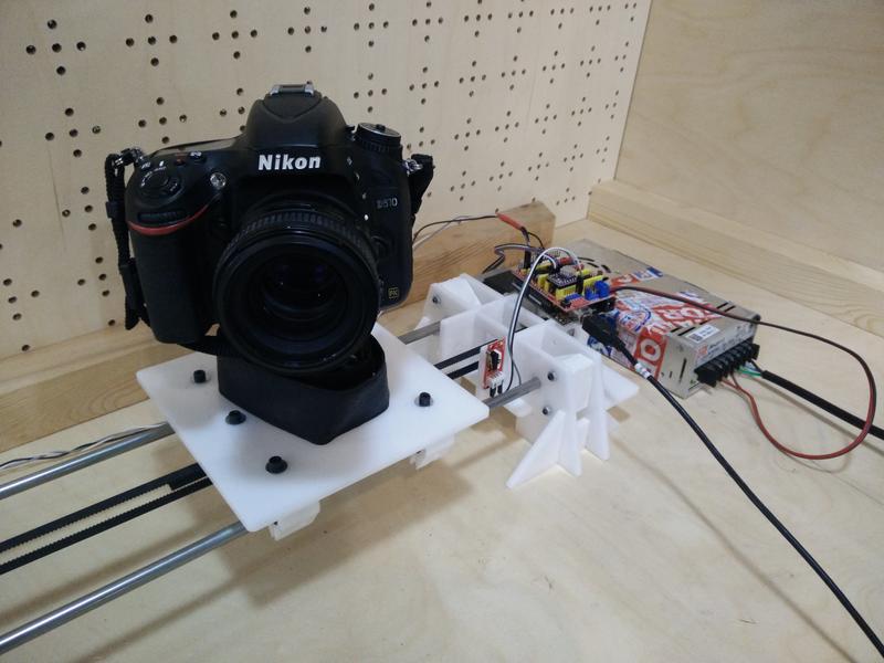
Testing the motor on our machine
First of all we had to register the torque/current limit supplied to the motor by the stepper driver. The DRV8825 has a potentiometer which lets you regulate this setting. Later on I found this useful guide for this process.
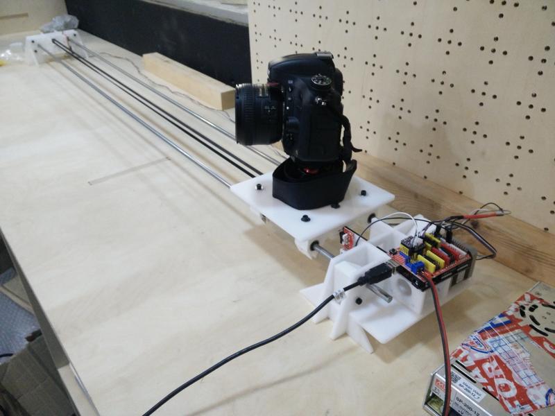
After registering the current limit here is the functioning prototype assembled on our machine.
A little bit of adjustment was necessary to find the correct steps frequency and belt tension to avoid vibrations but still have a slow movement of the platform.
Adding endstops
We started thiking at different ways to add the endstops to the dolly structure and ended up with a simple glue solution :) 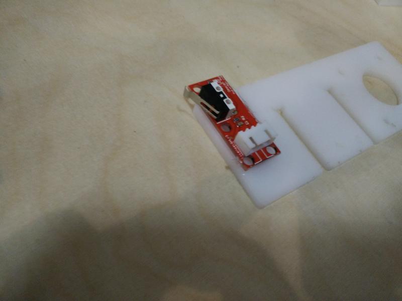
Here is the endstop assembled with the machine. 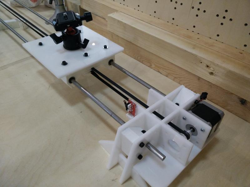
Firmware
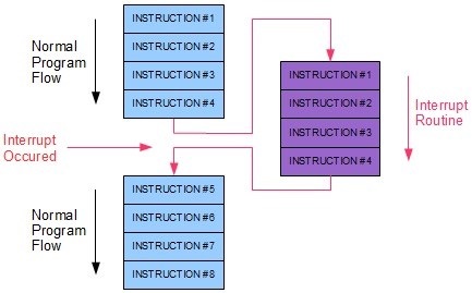
In terms of firmware, we had a look at the possibilities of using the end-stops with an ISR (Interrupt Service Routine), in order to do it the neat way:
We will be using an Arduino Uno with an ATMEGA328P-PU, which has a wide range of digital pins to be used. However, not all the pins can be used for an Interrupt with the attachInterrupt() function as stated in this link, and the hat we are using is definitively not using only those (2 and 3). Therefore, we would need to use the ISR in a different way. One good documentation about it is the one from Nick Gammon’s. From his site, a brief description of interrupts would define them as a way to let you respond to “external” events while doing something else.
For the ATMEGA328, below there is a list of available interrupts, in order of priority:
 1  Reset
 2  External Interrupt Request 0  (pin D2)          (INT0_vect)
 3  External Interrupt Request 1  (pin D3)          (INT1_vect)
 4  Pin Change Interrupt Request 0 (pins D8 to D13) (PCINT0_vect)
 5  Pin Change Interrupt Request 1 (pins A0 to A5)  (PCINT1_vect)
 6  Pin Change Interrupt Request 2 (pins D0 to D7)  (PCINT2_vect)
 7  Watchdog Time-out Interrupt                     (WDT_vect)
 8  Timer/Counter2 Compare Match A                  (TIMER2_COMPA_vect)
 9  Timer/Counter2 Compare Match B                  (TIMER2_COMPB_vect)
10  Timer/Counter2 Overflow                         (TIMER2_OVF_vect)
11  Timer/Counter1 Capture Event                    (TIMER1_CAPT_vect)
12  Timer/Counter1 Compare Match A                  (TIMER1_COMPA_vect)
13  Timer/Counter1 Compare Match B                  (TIMER1_COMPB_vect)
14  Timer/Counter1 Overflow                         (TIMER1_OVF_vect)
15  Timer/Counter0 Compare Match A                  (TIMER0_COMPA_vect)
16  Timer/Counter0 Compare Match B                  (TIMER0_COMPB_vect)
17  Timer/Counter0 Overflow                         (TIMER0_OVF_vect)
18  SPI Serial Transfer Complete                    (SPI_STC_vect)
19  USART Rx Complete                               (USART_RX_vect)
20  USART, Data Register Empty                      (USART_UDRE_vect)
21  USART, Tx Complete                              (USART_TX_vect)
22  ADC Conversion Complete                         (ADC_vect)
23  EEPROM Ready                                    (EE_READY_vect)
24  Analog Comparator                               (ANALOG_COMP_vect)
25  2-wire Serial Interface  (I2C)                  (TWI_vect)
26  Store Program Memory Ready                      (SPM_READY_vect)
The D2 and D3 pins are the ones mentioned in the Arduino documentation. However, we will be using the pins D8 to D13 with the PCINT0_vect services. For that we will have to write our own strategy, and to make it right we used the one from grbl, first by defining an interrupt function on the PCINT0_vect pins:
#define LIMIT_INT_vect   PCINT0_vect

ISR(LIMIT_INT_vect) // DEFAULT: Limit pin change interrupt process.
{

uint8_t state = limits_get_state();
  switch (state) {
      case 1:
        dir = false;
        break;
      case 0:
        dir = true;
        break;
  }
}
This function checks the status of the pins whenever triggered via the function limits_get_state():
uint8_t limits_get_state()
{
  uint8_t limit_state = 2;

  if (digitalRead(9)==HIGH && digitalRead(10)==LOW){
    limit_state = 1;
  }
  if (digitalRead(9) == LOW && digitalRead(10)==HIGH) {
    limit_state = 0;
  }

  // The first time we home, we don't do it again
  if (!home){
    home = true;
  }

  return(limit_state);
}
This surely can be done in a much more efficient way, but it serves our purposes: we are checking every time an ISR is coming on the digital pins of PCINT0vect which one of the two are HIGH, either the pin 9 or the pin 10. In case of not having done the _homing yet, we set the home flag to true, to change the movement settings from fast to slow. The variable containing which direction is the motor turning is changed accordingly and is sent in the main loop:
void loop(){

  //While not homed, move fast!
  while (home==false) {
    move(dir,X_DIR, X_STP, stepsFast, delayTimeFast);
  }

  //Now move nicely
  move(dir, X_DIR, X_STP, stepsSlow, delayTimeSlow); //X, Clockwise

}
Finally, as a remark, the registers are enabled in the setup() function as defined below:
#define LIMIT_DDR        DDRB
#define LIMIT_PIN        PINB
#define LIMIT_PORT       PORTB
#define X_LIMIT_BIT      1  // Uno Digital Pin 9
#define Y_LIMIT_BIT      2  // Uno Digital Pin 10
#define LIMIT_MASK ((1<<X_LIMIT_BIT)|(1<<Y_LIMIT_BIT)) // All limit bits
#define LIMIT_INT        PCIE0  // Pin change interrupt enable pin
#define LIMIT_PCMSK      PCMSK0 // Pin change interrupt register

void limits_init()
{
  LIMIT_DDR &= ~(LIMIT_MASK); // Set as input pins

  LIMIT_PORT |= (LIMIT_MASK);  // Enable internal pull-up resistors. Normal high operation.

  LIMIT_PCMSK |= LIMIT_MASK; // Enable specific pins of the Pin Change Interrupt
  PCICR |= (1 << LIMIT_INT); // Enable Pin Change Interrupt

}
This turns to do the following:
Download Sources (.zip archive)
Final result
And now! The final result of our work!
And here a sample video of our Sloth time-lapse recording!!!
\o/ \o/
Lessons learned
- How to drive a stepper motor! :)
- When we built our final structure, we made assumptions about the motor and drive mechanism: ideally we should be iterating on the mechanical structure once we learned about the components used.
- Driving a single motor is quite easy in code and we do not require a more complex CNC shield for this.
Next steps
- Add a speed control potentiometer.
- Optimize for battery powered components.
- Try smaller 5V stepper motor with gearing: eg. this.
- Try wiring the stepper driver without using the CNC shield.
- Design a better enclosure and wiring of the electronic parts.